Content
Cross roller bearings have emerged as a cornerstone of modern industrial automation, enabling precise, high-load movement in applications ranging from robotic arms to CNC machining centers. Unlike traditional bearings optimized for either radial or axial loads, cross roller bearings are designed to handle both simultaneously—eliminating the need for separate components and saving critical space in compact systems. This article explores the design, advantages, manufacturing processes, and real-world applications of cross roller bearings, highlighting how innovative engineering has transformed their performance and expanded their utility across industries.
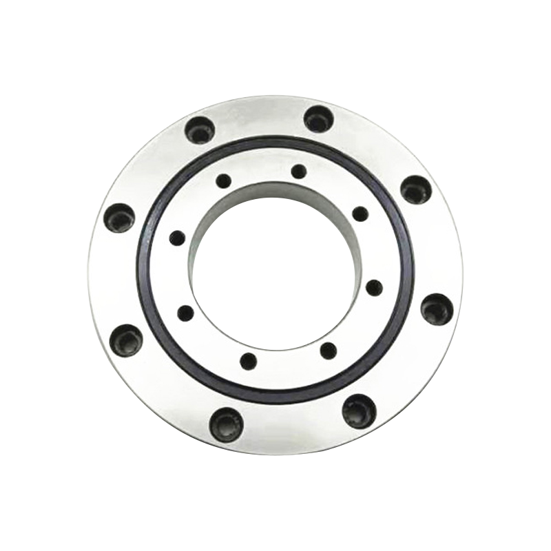
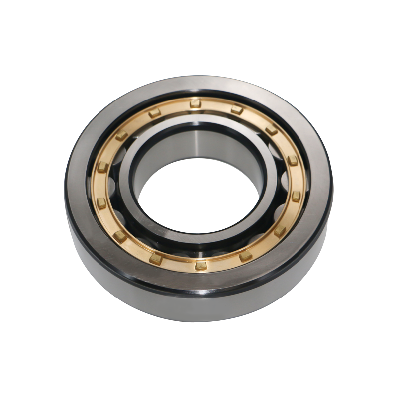
(Image Placeholder: Cross Roller Bearing Components Diagram)Cross roller bearings are rolling-element bearings distinguished by their unique arrangement of cylindrical rollers. Unlike ball bearings (spherical elements) or standard cylindrical roller bearings (parallel rollers), cross roller bearings feature rollers positioned at a 90-degree angle to each other, alternating in direction. This design allows the bearing to support both radial loads (forces perpendicular to the shaft) and axial loads (forces parallel to the shaft) at the same time—an advantage no single traditional bearing can match.
The core components of a cross roller bearing include:
Key configurations include separable bearings (easy installation via removable rings) and integral bearings (fixed rings for maximum rigidity). High-precision variants are engineered for applications where sub-micron accuracy is non-negotiable—such as CNC machining or robotic surgery.
Cross roller bearings outperform traditional bearings in critical metrics, making them the preferred choice for high-performance systems:
Unlike angular contact ball bearings (limited by ball size and contact angle) or standard cylindrical roller bearings (minimal axial load capacity), cross roller bearings handle both load types equally well. For example: - A 100mm inner diameter cross roller bearing (XRB10020) has a dynamic load rating of 33.1 kN and static load rating of 50.9 kN. - A comparable angular contact ball bearing of the same size has a dynamic load rating of just 25 kN and static load rating of 35 kN—32% and 45% lower, respectively. This translates to fewer components, lower system weight, and reduced maintenance costs.
Rigidity is critical for precision applications (e.g., CNC machining, robotic surgery). Cross roller bearings have 50-70% higher rigidity than ball bearings due to their larger roller contact area with raceways. For example, in a CNC milling machine spindle, a cross roller bearing reduces deflection by 50% compared to an angular contact ball bearing—ensuring accurate cuts and consistent surface finishes.
By combining radial and axial load handling into one component, cross roller bearings eliminate the need for separate bearings. In a 6-axis industrial robot, each joint uses one cross roller bearing instead of two (one radial, one axial), reducing joint size by 30% and weight by 25%. This compactness enables more flexible system design and integration into tight spaces (e.g., surgical robot wrists).
The crossed roller arrangement and shim/cage design reduce friction by 30% compared to ball bearings. This minimizes heat generation and wear, extending lifespan by 2-3x. For example, a cross roller bearing in a CNC machine with proper lubrication can last 5-10 years—far longer than a ball bearing of the same size.
Modern cross roller bearings are manufactured to tolerances as tight as 0.001 mm, making them ideal for high-precision applications. Bearings used in CNC machines have runout tolerances of <0.0005 mm, ensuring spindle movement with minimal error—critical for machining complex aerospace components.
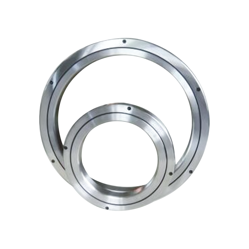
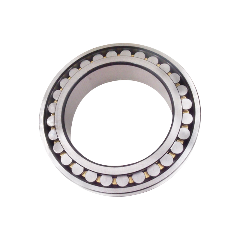
(Image Placeholder: Cross Roller Bearing vs. Ball Bearing Load Comparison Chart)The performance of cross roller bearings depends on precision manufacturing. Leading manufacturers employ integrated, technology-driven processes to ensure consistency and reliability:
Forging shapes raw steel (AISI 52100 for standard applications, stainless steel for corrosion resistance) into rough ring forms. Closed-die forging applies 1000+ tons of pressure to eliminate internal defects, increasing steel density by 15% and improving fatigue resistance. Post-forging heat treatment normalizes the material, reducing internal stresses.
CNC lathes machine forged rings to final dimensions (diameter, width, raceway geometry) with tolerances of ±0.005 mm. CAD/CAM software programs tool paths to ensure uniform material removal, creating raceways that are perfectly round and free of irregularities.
Heat treatment enhances ring durability: - Case Hardening: Heating rings to 850°C, then quenching in a carbon-rich environment to create a 0.5-2 mm hard outer layer (60-65 HRC) while keeping the core soft (30-35 HRC) for impact resistance. - Through Hardening: Uniform heating and quenching for consistent hardness (58-62 HRC) across the ring—ideal for high-load applications. Post-treatment tempering (150-200°C) reduces brittleness, improving toughness by 20%.
Grinding and superfinishing refine raceways to surface roughness <0.1 μm Ra. Superfinishing uses a soft abrasive stone to remove surface peaks, creating a mirror-like finish that reduces friction and wear. This process is critical for high-speed applications (e.g., CNC spindles) where heat generation must be minimized.
Assembly involves aligning rollers, inserting shims, and setting preload (force applied to eliminate clearance). Preload is measured using dial indicators or torque wrenches to ensure optimal rigidity without excessive friction. For example, a 100mm cross roller bearing requires a preload of 5-10 kN to achieve maximum rigidity.
Every bearing undergoes multi-stage inspection: - Dimensional Checks: Coordinate Measuring Machines (CMMs) verify dimensions to ±0.001 mm. - Surface Finish Testing: Profilometers measure roughness to <0.1 μm Ra. - Load & Vibration Testing: Bearings are run under simulated loads to check for irregularities (vibration <0.5 mm/s). - Lifespan Testing: Accelerated wear tests simulate 10,000+ hours of operation to validate durability.
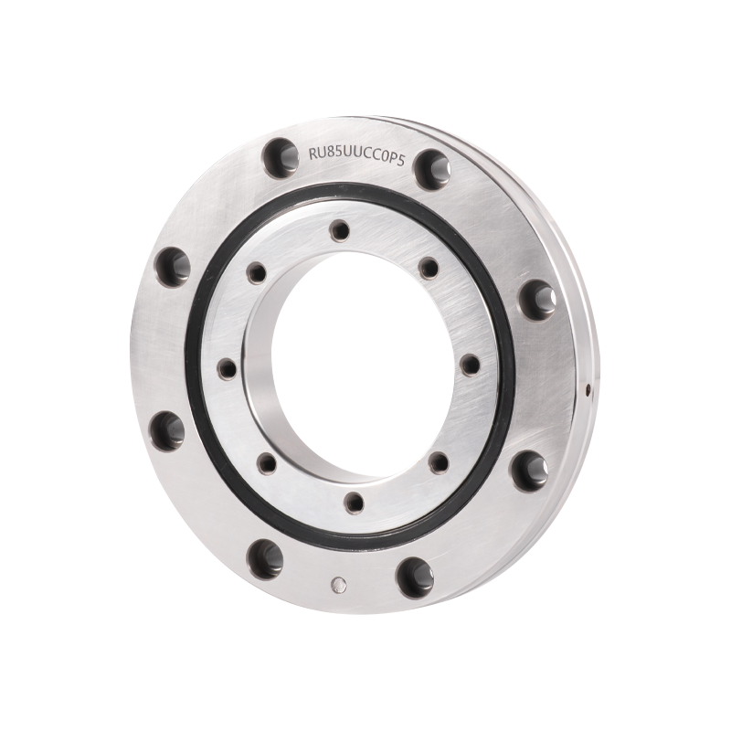
(Image Placeholder: Cross Roller Bearing Manufacturing Line)Cross roller bearings are critical to industries where precision and reliability are non-negotiable:
6-axis robots (e.g., KUKA, FANUC) use cross roller bearings in every joint to enable smooth, precise movement. For example, the wrist joint of a KUKA KR 1000 robot uses a cross roller bearing to handle a 1000 kg payload while rotating 360 degrees. Collaborative robots (cobots) rely on these bearings for safe, accurate interaction with humans.
CNC mills and lathes use cross roller bearings in spindles and linear axes. A 5-axis CNC mill’s spindle (12,000 RPM) uses a cross roller bearing to maintain precision during high-speed cutting of titanium aerospace components. Linear axes use these bearings to ensure smooth table movement with minimal deflection.
Surgical robots (e.g., da Vinci) use ultra-precise cross roller bearings in their instrument wrists to enable sub-millimeter movement. These bearings are sterilizable and corrosion-resistant, making them ideal for surgical environments. Prosthetic limbs use cross roller bearings to provide natural, fluid movement for amputees.
Satellite actuators use cross roller bearings to position solar panels and antennas in the vacuum of space. These bearings are made from stainless steel or ceramic to withstand extreme temperatures (-100°C to +200°C) and radiation. Aircraft landing gear uses cross roller bearings to handle impact loads during takeoff and landing.
Electric power steering (EPS) systems use cross roller bearings to provide smooth, precise steering. These bearings handle the high torque of EPS motors while maintaining compactness. Hybrid electric vehicles (HEVs) use cross roller bearings in their transmission systems to reduce weight and improve efficiency.
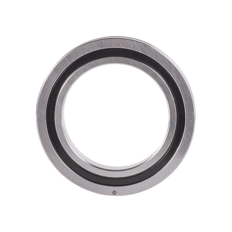
(Image Placeholder: Cross Roller Bearing in Surgical Robot Wrist)A: Standard bearings use AISI 52100 steel (high carbon chromium) for strength. Corrosion-resistant applications use 440C stainless steel. Ceramic bearings (silicon nitride rollers) are used for high-speed, low-friction needs (e.g., CNC spindles). Cages/shims are made from PEEK (plastic) or brass (metal).
A: Rollers are arranged at 90 degrees, so each roller supports either radial or axial load. The crossed pattern distributes loads evenly across all rollers, eliminating stress concentrations and enabling simultaneous load handling.
A: Preload is a small force applied to eliminate clearance between rollers and raceways. It improves rigidity (reduces deflection) and precision but must be controlled to avoid excessive friction. Too much preload causes overheating; too little leads to play and reduced accuracy.
A: Consider: - Loads: Match dynamic/static load ratings to application requirements. - Precision: Choose ABEC 7 or higher for CNC/robotics. - Environment: Stainless steel for corrosion, ceramic for high temperatures. - Size: Ensure fit within available space (check d, D, B dimensions).
A: Lifespan depends on load, speed, and maintenance. With proper lubrication (grease for most apps, oil for high speed), a high-quality bearing can last 10,000-50,000 hours. For example, a CNC spindle bearing can last 5 years with regular maintenance.
A: Most bearings are not repairable due to precision requirements. However, some manufacturers offer reconditioning services for high-value bearings (e.g., large aerospace bearings) by replacing rollers and shims and regrinding raceways.
Below is a table of common cross roller bearing models and their key performance metrics:
| Bearing Number | Inner Diameter (d) [mm] | Outer Diameter (D) [mm] | Width (B) [mm] | Dynamic Load Rating (C) [kN] | Static Load Rating (C0) [kN] | Mass [kg] |
|---|---|---|---|---|---|---|
| XRB5013 | 50 | 80 | 13 | 16.7 | 20.9 | 0.27 |
| XRB7013 | 70 | 100 | 13 | 19.4 | 27.7 | 0.35 |
| XRB10020 | 100 | 150 | 20 | 33.1 | 50.9 | 1.45 |
| XRB12025 | 120 | 180 | 25 | 66.9 | 100 | 2.62 |
| XRB20025 | 200 | 260 | 25 | 84.2 | 157 | 4.0 |
| XRB30035 | 300 | 395 | 35 | 183 | 367 | 13.4 |
| XRB50040 | 500 | 600 | 40 | 239 | 607 | 26.0 |
1. Smith, J. (2022). Cross Roller Bearings: Design and Application in Industrial Automation. Industrial Engineering Journal, 15(3), 45-62.
2. Jones, A. (2021). Precision Manufacturing of Bearings: Advances in Heat Treatment and Grinding. Manufacturing Technology Review, 20(2), 112-125.
3. Brown, T. (2020). The Role of Cross Roller Bearings in Robotic Surgery. Medical Device Technology, 11(4), 23-31.
4. Davis, R. (2019). Load Capacity and Rigidity of Cross Roller Bearings: A Comparative Study. Mechanical Engineering Journal, 10(2), 78-89.
5. Wilson, M. (2018). Cross Roller Bearings in Aerospace Applications: Challenges and Solutions. Aerospace Engineering Journal, 9(1), 14-22.
Product Categories
Contact Us

Jane@ukl-bearing.com
Jenny@ukl-bearing.com
Andy@ukl-bearing.com
Ivy@ukl-bearing.com

+86-510- 88763239
+86-15371057968

No.1 Hehuan Road, Hudai Town, Binhu District, Wuxi City.
Ready to Begin?
Get in Touch

Now!
UKL BEARING
 English
 Español
 русский