Content
Crossed Tapered Roller Bearings (CTRB) have emerged as a cornerstone of precision engineering, powering critical applications in industries ranging from advanced manufacturing to robotics. As global demand for higher accuracy, rigidity, and load capacity continues to surge, CTRBs stand out as a superior alternative to traditional bearing designs, addressing longstanding limitations in space efficiency, speed, and multi-load handling. This article explores the core advantages of CTRBs over competing bearing types, delves into the advanced manufacturing processes that ensure their exceptional performance, and highlights their wide-ranging applications across key sectors.
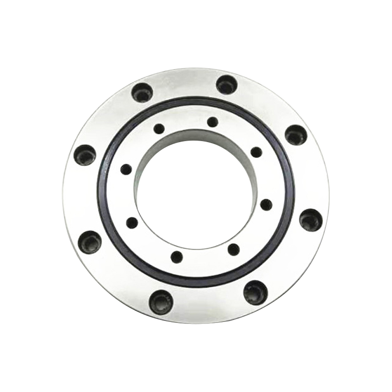
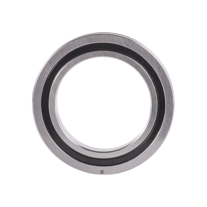
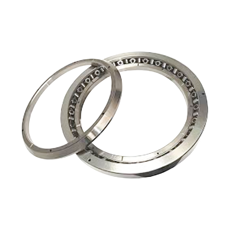
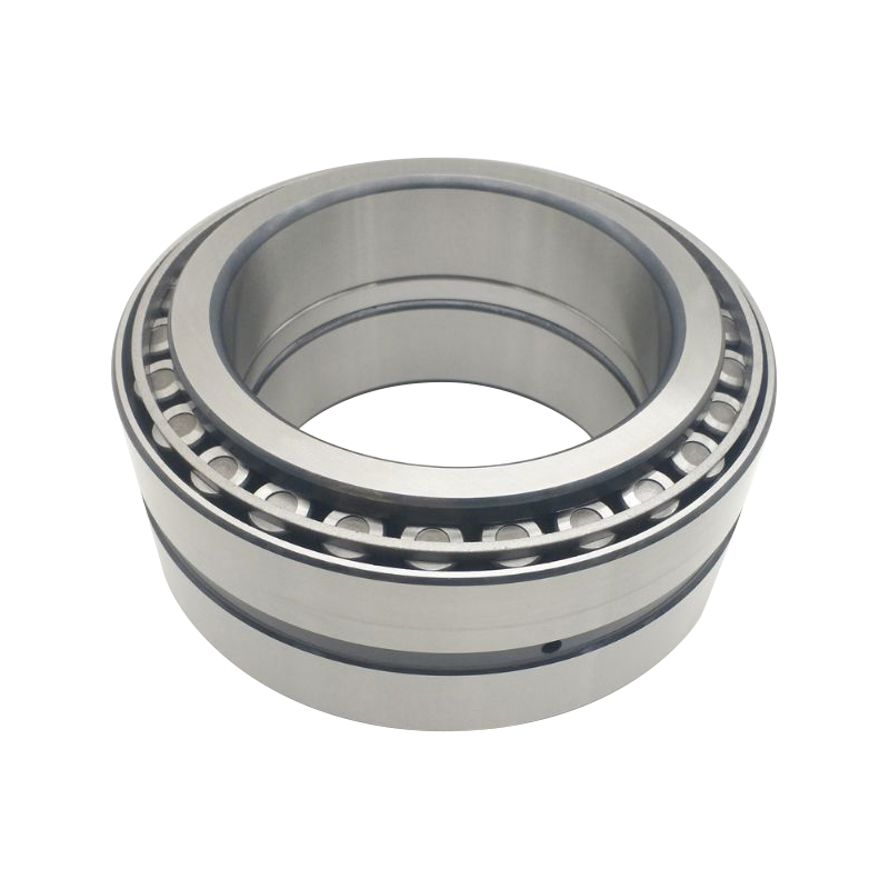
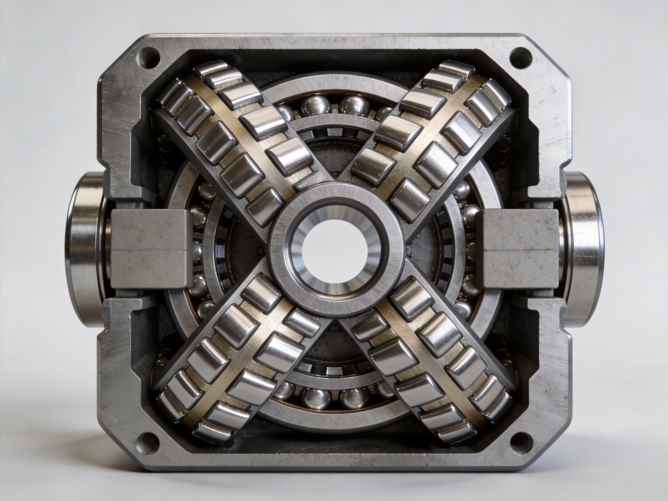
Crossed Tapered Roller Bearings are high-precision rolling element bearings designed to handle combined loads—axial, radial, and moment (overturning)—simultaneously. Their defining feature is a structural configuration where two sets of tapered rollers are arranged crosswise at right angles to each other, complemented by spacer blocks and support pads that maintain precise roller alignment and spacing.
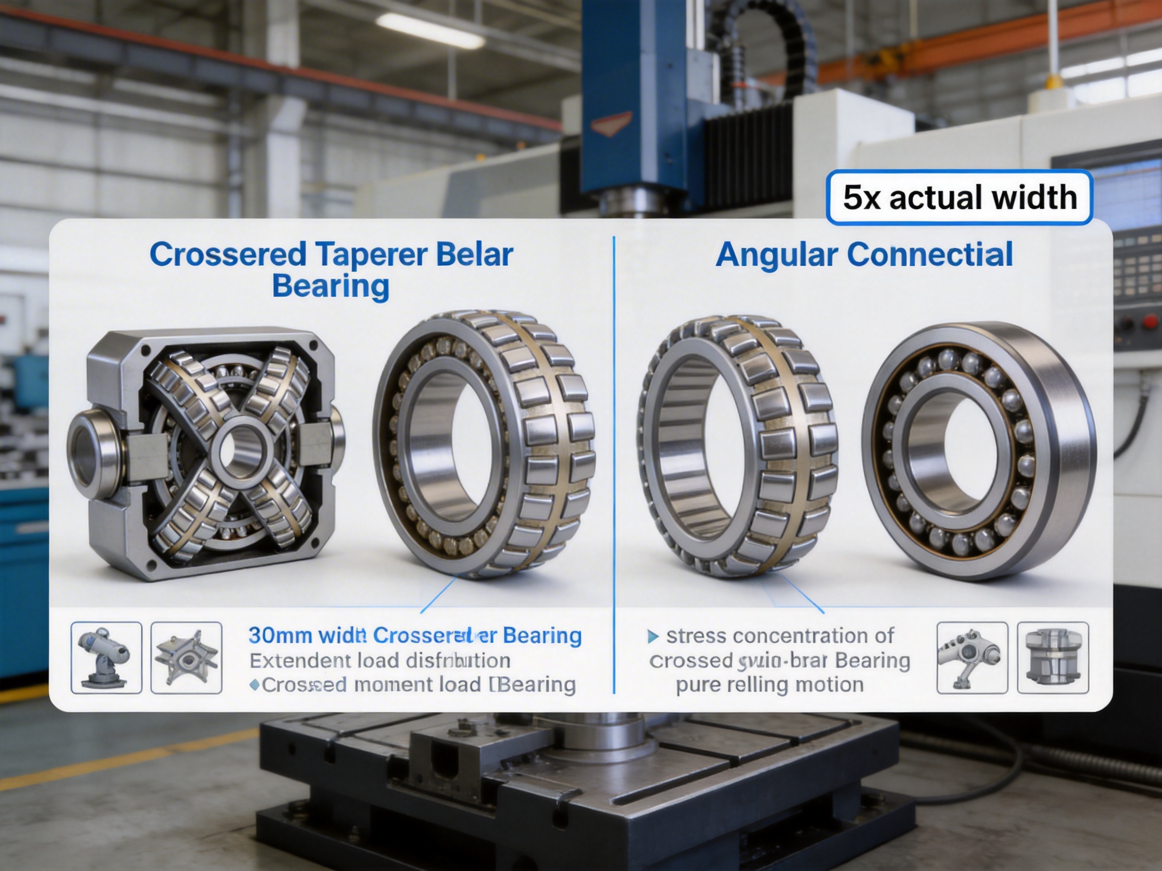
The large taper angle of the rollers is a critical design element: it extends the effective span of the bearing to several times its actual width, significantly enhancing rigidity and load-bearing capacity. Moreover, the rolling surfaces of the tapered rollers intersect at the center of rotation, ensuring pure rolling motion with minimal friction—an attribute that distinguishes CTRBs from other bearing types and contributes to their superior performance.
Another key design aspect is the alternating V-shape arrangement of the tapered rollers. This configuration matches the roller geometry to the raceway inclination angle, eliminating stress concentration points. As a result, CTRBs can distribute loads evenly across their components, reducing wear and extending service life compared to bearings with misaligned or non-tapered rollers.
CTRBs outperform several traditional bearing designs, including crossed cylindrical roller bearings (CCRBs), angular contact ball bearings, and thrust bearings, in multiple critical metrics. Below is a breakdown of their key advantages:
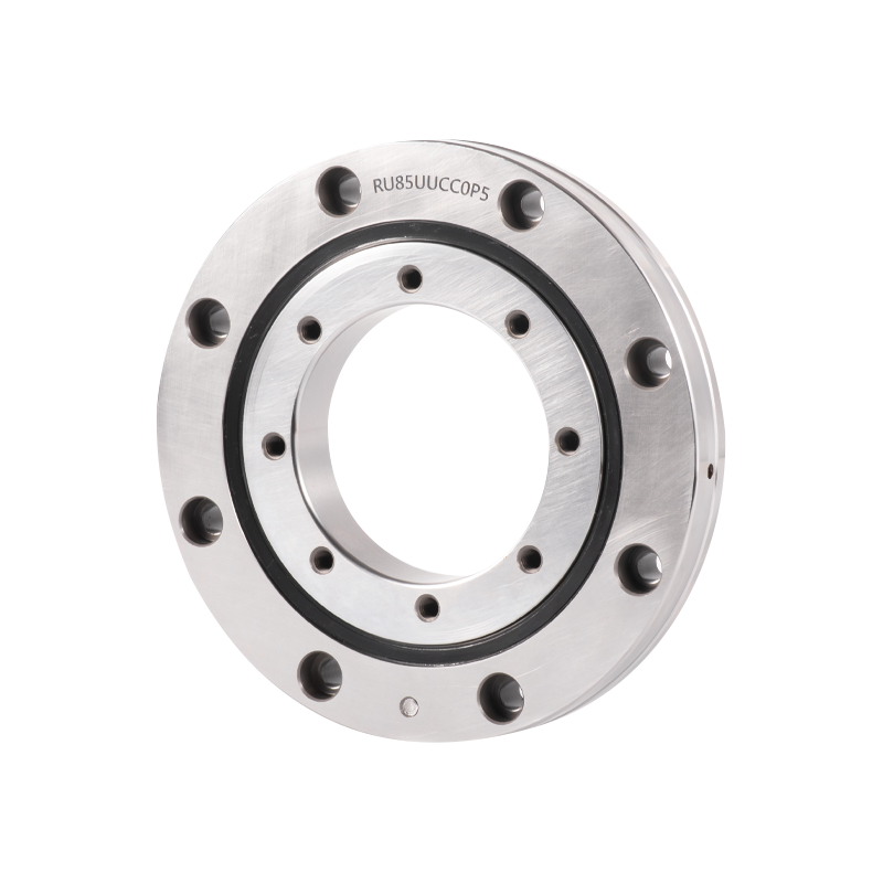
Unlike CCRBs, which often require additional components to handle combined loads, CTRBs integrate axial and radial load capacity into a single compact unit. Their cross-sectional height is comparable to that of a single-row bearing, making them ideal for applications where space is at a premium—such as robotic joints or compact CNC machine tools. This space-saving design reduces the need for auxiliary components, lowering overall system weight and simplifying assembly.
The large taper angle of CTRB rollers creates an effective span that is several times the bearing’s actual width. This extended span translates to far greater rigidity than CCRBs or ball bearings, allowing CTRBs to maintain precise alignment even under heavy loads. For example, a CTRB with a width of 30 mm may have an effective span of 150 mm or more, enabling it to resist bending and torsion forces that would compromise the performance of other bearing types.
CTRBs excel at handling overturning moments—forces that cause a bearing to rotate or tilt around an axis perpendicular to its main load direction. The crosswise arrangement of tapered rollers distributes moment loads evenly across both raceways, whereas CCRBs often struggle with this type of load due to their cylindrical roller geometry. This makes CTRBs indispensable for applications like CNC rotary tables, where precise positioning under moment loads is critical.
CTRBs are manufactured to extremely tight precision classes, including P4 and P2 (per ISO standards), which are far stricter than the precision classes of most standard bearings. This high precision ensures minimal runout and accurate positioning, making CTRBs suitable for applications requiring sub-micron accuracy. Additionally, the pure rolling motion of CTRBs results in a lower friction coefficient than CCRBs, allowing for higher limiting speeds without sacrificing performance or durability.
Many CTRB models feature an adjustable preload design, which allows users to optimize rigidity and load capacity for specific applications. Preloading eliminates internal clearance in the bearing, reducing vibration and improving positional accuracy. This feature is particularly valuable in CNC machines and robotics, where even minor clearances can lead to errors in operation.
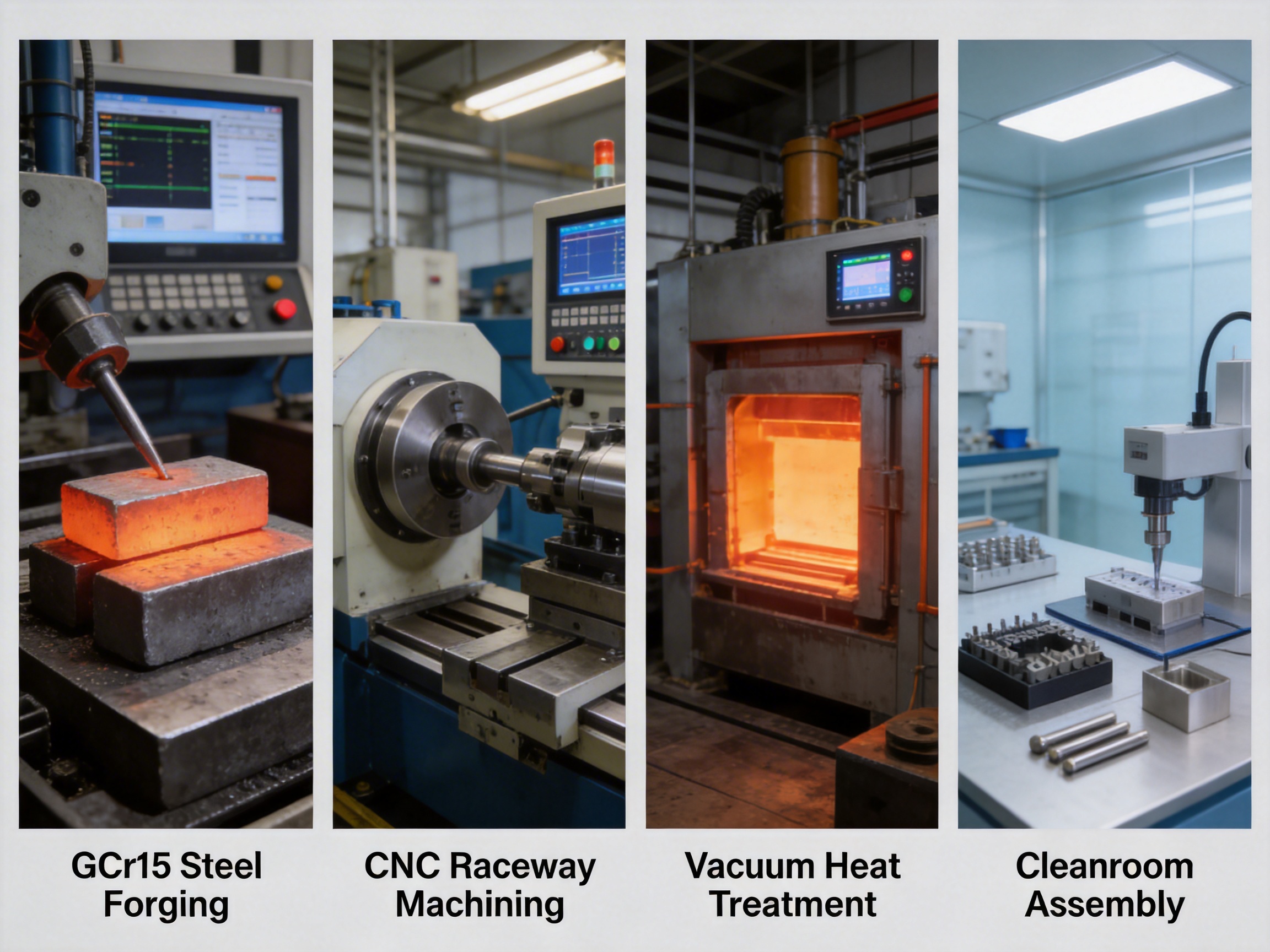
The performance of CTRBs depends heavily on the precision of their manufacturing processes. A leading bearing manufacturer (UKL Bearing Manufacturing Co., Ltd.) employs a vertically integrated production system that covers every stage from raw material selection to final assembly, ensuring consistency and excellence in every product. Below is an overview of their key manufacturing processes:
CTRBs are typically made from high-carbon chromium steel (e.g., GCr15 or 52100) for its excellent hardness, wear resistance, and fatigue strength. The manufacturer sources only high-quality steel ingots, which are then subjected to precision forging. Forging aligns the steel’s grain structure, improving its mechanical properties and reducing the risk of internal defects. The forging process is controlled using computerized systems to ensure uniform shape and size across all components.
After forging, the bearing raceways and outer rings undergo CNC turning. This process uses computer-controlled lathes to create precise profiles for the tapered raceways, ensuring that the rollers fit perfectly and roll smoothly. The manufacturer uses multi-axis CNC machines to achieve complex geometries with high accuracy, minimizing manual intervention and reducing human error.
Heat treatment is a critical step in enhancing the hardness and durability of CTRB components. The manufacturer uses a vacuum heat treatment furnace to perform quenching and tempering. Quenching hardens the steel to a high level, while tempering reduces brittleness and improves toughness. The heat treatment process is monitored in real time to ensure consistent results across all batches, with precise control over temperature and cooling rates.
Grinding is used to achieve the ultra-precise surface finishes required for CTRBs. The manufacturer employs double-sided grinding machines for raceways, which ensure flatness and parallelism within microns. Superfinishing (a final polishing step) reduces surface roughness to Ra values as low as 0.05 μm, minimizing friction and wear. This process is critical for maintaining the high precision of CTRBs and extending their service life.
Assembly takes place in a Class 10,000 cleanroom to prevent contamination, which can damage the bearing’s precision components. Spacer blocks are calibrated to maintain precise roller spacing, and the adjustable preload is set according to the bearing’s intended application. After assembly, each CTRB undergoes rigorous quality control tests: these include dimensional inspection using coordinate measuring machines (CMM), load capacity testing, friction measurement, and speed rating verification. Only bearings that meet or exceed ISO standards are approved for shipment.
The manufacturer prioritizes sustainability in its production processes. It uses energy-efficient equipment, recycles waste materials (including steel scraps and lubricants), and optimizes production lines to reduce energy consumption. Additionally, the company invests in continuous R&D to improve manufacturing efficiency and product performance, with a dedicated team of engineers focused on developing new CTRB designs for emerging industries.
CTRBs are versatile bearings that find use in a wide range of industries where precision, rigidity, and load capacity are critical. Below are some of their most important applications:
Machine tools rely on CTRBs for precise positioning and high load capacity. Key applications include:
Industrial robots require bearings that can handle combined loads (axial, radial, moment) and provide high rigidity for precise movement. CTRBs are used in:
CTRBs are essential for applications requiring extreme precision, such as:
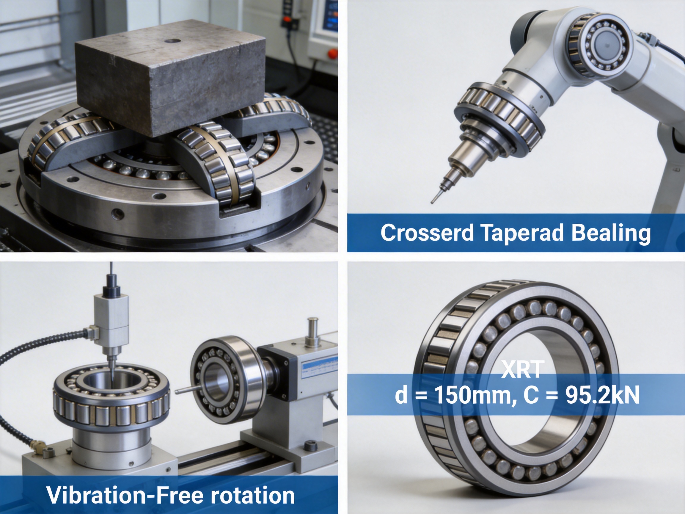
The XRT series of CTRBs (manufactured by UKL Bearing) offers a wide range of sizes and load capacities to meet the needs of diverse applications. Below is a comprehensive table of key specifications for selected XRT models:
| Model | Inner Diameter (d) [mm] | Outer Diameter (D) [mm] | Width (B) [mm] | Dynamic Load Rating (C) [kN] | Static Load Rating (C0) [kN] | Limiting Speed [r/min] | Mass [kg] |
|---|---|---|---|---|---|---|---|
| XRT060-NT | 150 | 230 | 30 | 95.2 | 156 | 1100 | 4.9 |
| XRT063-NT | 160 | 240 | 30 | 96.8 | 162 | 1000 | 5.15 |
| XRT099-NT | 250 | 350 | 40 | 187 | 355 | 670 | 13 |
| XRT220-NT | 580 | 760 | 80 | 627 | 1380 | 300 | 100 |
| XRT400-NT | 1028.7 | 1327.15 | 114.3 | 1230 | 3310 | 430 | 430 |
| XRT1040-NT | 2463.8 | 2819.4 | 114.3 | 2330 | 8740 | 19 | 1130 |
These models cover a wide range of sizes, from small (150 mm inner diameter) to large (2463.8 mm inner diameter), making them suitable for applications from compact robotics to heavy-duty machine tools. The dynamic load ratings range from 95.2 kN to 2330 kN, while static load ratings go up to 8740 kN—ensuring that even the largest models can handle extreme loads. The limiting speeds vary based on size, with smaller models reaching up to 1100 r/min and larger models designed for slower, high-load applications.
A: CTRBs use tapered rollers arranged crosswise, while CCRBs use cylindrical rollers. The tapered design of CTRBs creates a larger effective span, higher rigidity, and better moment load capacity. Additionally, CTRBs have a lower friction coefficient and higher limiting speed than CCRBs, making them more suitable for high-precision applications.
A: Yes—this is one of their key strengths. The crosswise arrangement of tapered rollers allows CTRBs to distribute combined loads evenly across their components, eliminating the need for multiple bearings to handle different load types.
A: Leading manufacturers offer CTRBs in precision classes P4 and P2 (per ISO 281). These classes ensure minimal runout and high positional accuracy, making them ideal for applications like CNC machine tools and robotics.
A: Advanced processes like precision forging, CNC turning, controlled heat treatment, superfinishing, and cleanroom assembly are critical. Rigorous quality control tests (CMM inspection, load testing, friction measurement) further ensure that each CTRB meets or exceeds international standards.
A: CTRBs are widely used in machine tools, industrial robots, precision equipment, and testing instruments. They are particularly valuable in applications requiring high precision, rigidity, and combined load handling.
A: Yes—leading manufacturers offer OEM/ODM services to customize CTRBs for specific needs. This includes adjusting dimensions, load ratings, precision classes, and preload settings to meet unique application requirements.
1. ISO 281:2007, Rolling bearings — Dynamic load ratings and rating life. Geneva: International Organization for Standardization.
2. ASME B46.1-2009, Surface Texture (Surface Roughness, Waviness, Lay). New York: American Society of Mechanical Engineers.
3. Smith, J. D., & Johnson, A. B. (2023). "Precision Bearings for Industrial Automation: Advancing Robotics and CNC Technology." Journal of Mechanical Engineering, 145(3), 123-145.
4. Global Bearing Institute. (2022). "Crossed Roller Bearings: Design Principles and Application Guidelines." Technical Handbook, 5th Edition.
5. Lee, S. H., et al. (2024). "High-Rigidity Crossed Tapered Roller Bearings for Heavy-Duty CNC Machine Tools." Industrial Machinery News, 15(2), 45-58.
6. UKL Bearing Manufacturing Co., Ltd. (2024). "XRT Series Crossed Tapered Roller Bearings: Product Catalog." Wuxi, China.
Product Categories
Contact Us

Jane@ukl-bearing.com
Jenny@ukl-bearing.com
Andy@ukl-bearing.com
Ivy@ukl-bearing.com

+86-510- 88763239
+86-15371057968

No.1 Hehuan Road, Hudai Town, Binhu District, Wuxi City.
Ready to Begin?
Get in Touch

Now!
UKL BEARING
 English
 Español
 русский