Content
Self-lubricating rod end spherical bearings are compact mechanical components designed to transfer loads while accommodating angular misalignment between connected parts. They are widely used in automation equipment, robotic mechanisms, industrial linkages, construction machinery, transportation systems, agricultural equipment, and many other applications where a fixed bearing arrangement cannot compensate for movement or alignment variation.
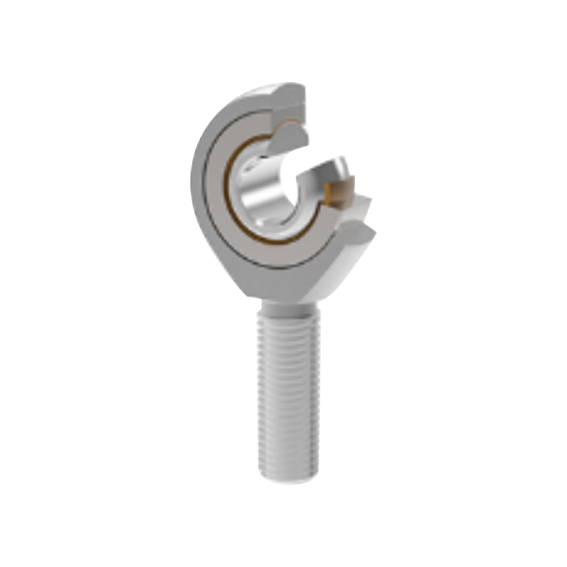
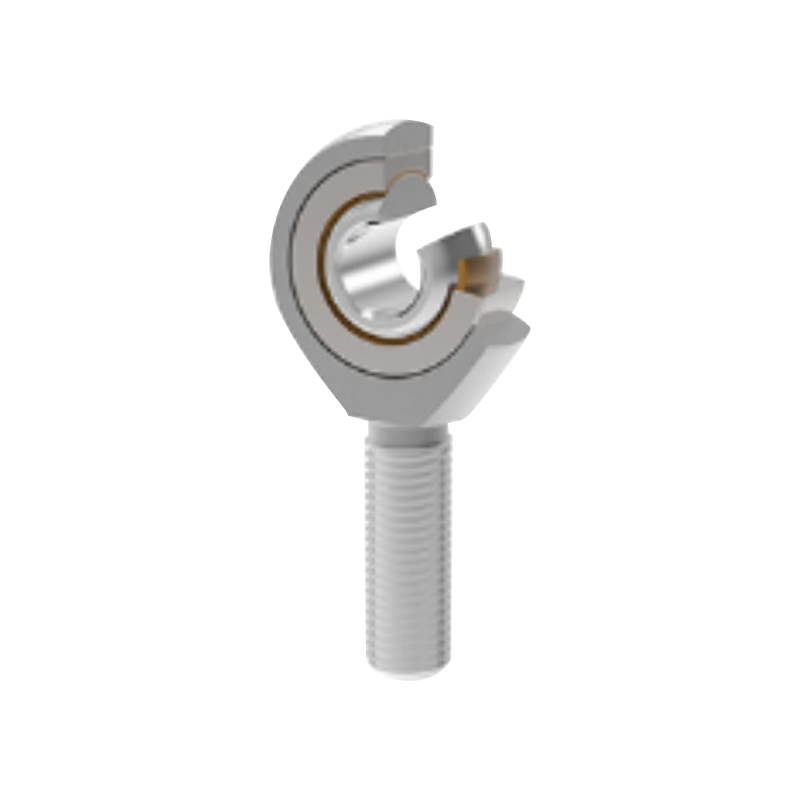
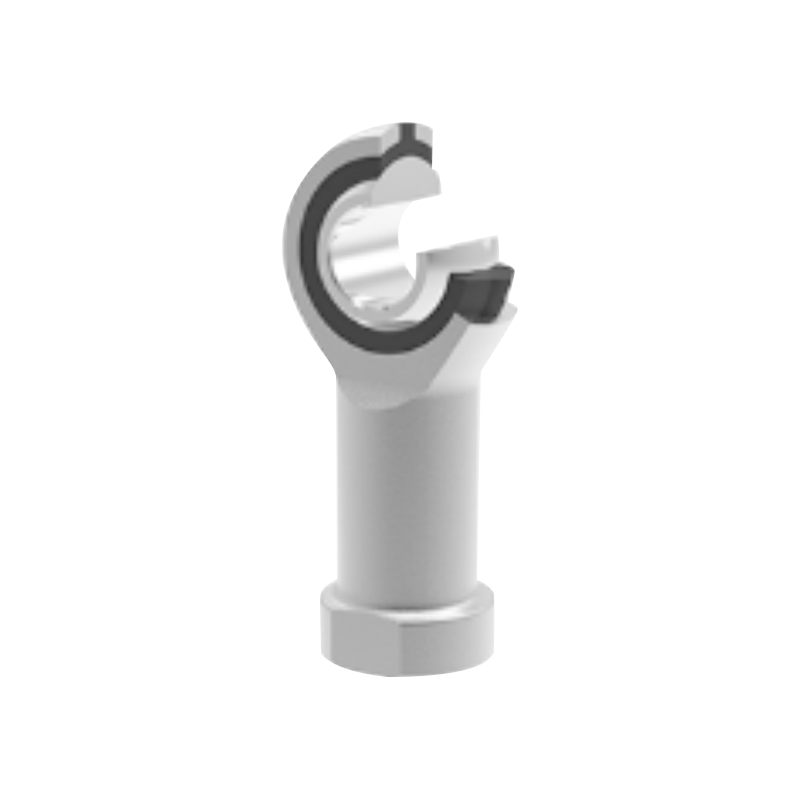
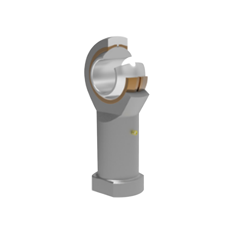
The SA self-lubricating rod end spherical bearing is engineered as an assembled unit consisting of a rod end body and a self-lubricating radial spherical bearing. This construction combines the installation convenience of a rod end with the maintenance advantages of a composite spherical bearing. The result is a practical solution for systems that require reliable oscillating motion, compact dimensions, low maintenance, and stable performance under demanding operating conditions.
Unlike conventional rod ends that depend on regular grease replenishment, the SA series uses a self-lubricating sliding friction pair. The SA…C version uses a steel and PTFE composite material, while the SA…ETL 2RS version uses a steel and PTFE braided fabric system. Both designs are intended to operate without external lubrication during normal service, helping simplify equipment maintenance and reducing the risk of lubricant contamination.
UKL Bearing Manufacturing Co., Ltd. supplies these rod end spherical bearings as part of its broader bearing portfolio, which includes cross roller bearings, angular contact ball bearings, cylindrical roller bearings, spherical roller bearings, tapered roller bearings, mounted bearings, and related industrial bearing products. Through integrated engineering, production, inspection, and export services, the company supports both standard bearing requirements and customized OEM or ODM projects.
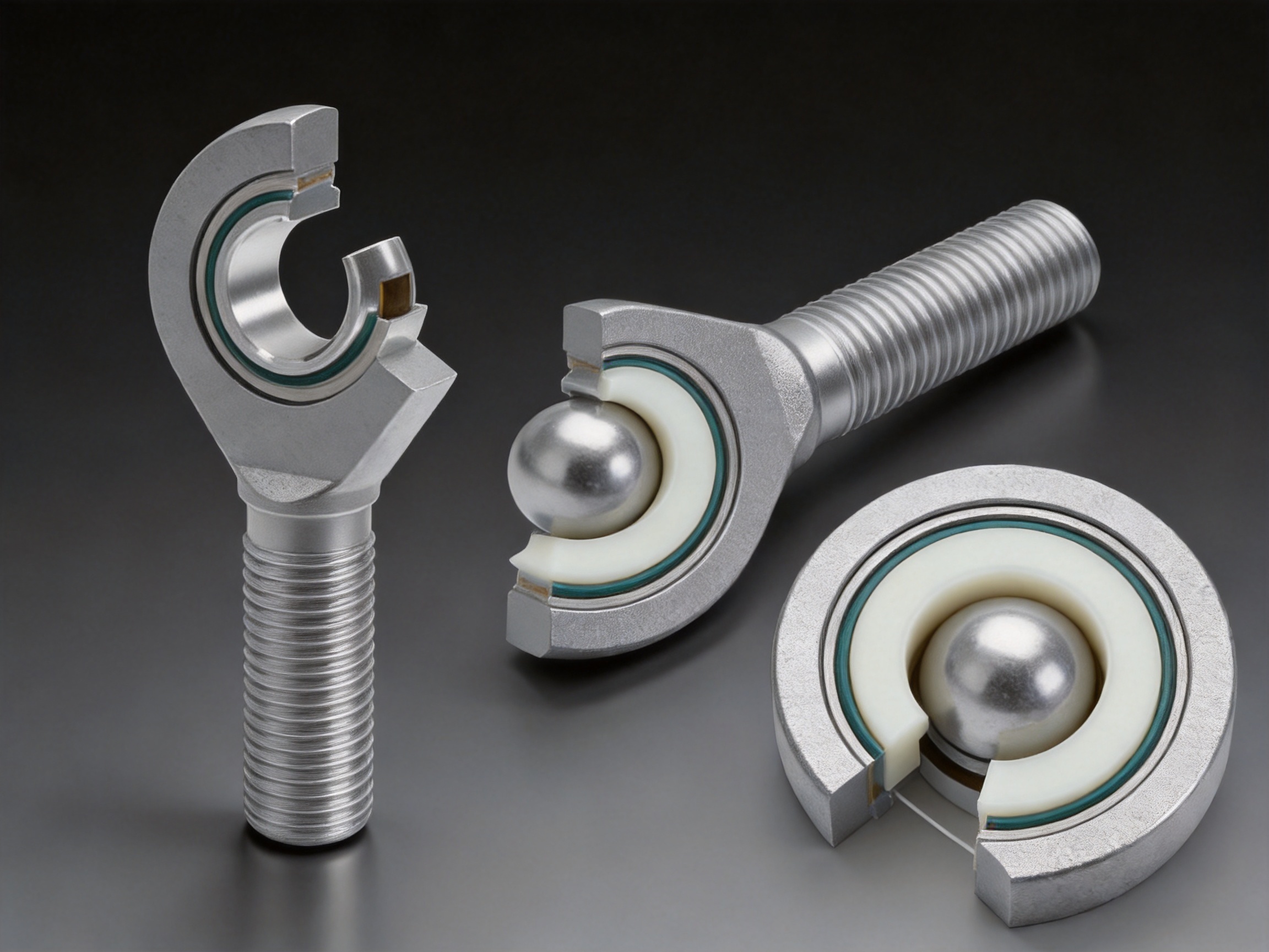
A rod end spherical bearing is a mechanical joint that combines a threaded rod end housing with a spherical plain bearing. The threaded shank allows the component to be attached to a machine frame, actuator, linkage, or support structure. The spherical bearing inside the eye-shaped head allows the mating shaft or pin to rotate and oscillate while also accommodating angular deviation.
The spherical sliding contact is especially useful in mechanisms where two connected components do not remain perfectly aligned throughout their operating cycle. A rigid connection may create excessive edge loading, binding, or premature wear. A spherical rod end allows the shaft to change its angle relative to the rod end body, thereby reducing alignment stress and helping the connected mechanism move more smoothly.
The SA series is assembled from two primary elements:
1. A rod end body manufactured from carbon steel and finished with a galvanized surface.
2. A self-lubricating radial spherical bearing installed within the rod end body.
The carbon steel body provides structural strength and thread stability. The galvanized surface improves resistance to ordinary atmospheric corrosion and provides a clean, durable exterior finish. The internal spherical bearing provides the sliding interface required for oscillating and misaligned motion.
Because the bearing is self-lubricating, the design does not require routine grease application in standard operating conditions. This is a significant advantage in applications where lubrication points are difficult to access, where grease could attract dust, or where regular maintenance would interrupt production.
During operation, the inner spherical element supports a shaft, pin, or mating component. The inner element can rotate or oscillate inside the spherical sliding surface. At the same time, the rod end body transfers radial loads to the threaded connection. The geometry allows angular movement without requiring the entire assembly to be perfectly aligned.
The load path begins at the shaft or pin, passes through the spherical bearing, transfers into the rod end body, and finally reaches the supporting structure through the threaded shank. Correct installation is therefore important. The shaft diameter, mounting direction, thread engagement, tightening method, and surrounding clearance all influence service life.
The sliding friction pair is the defining feature of the SA product family. In the SA…C version, the contact system is based on steel and PTFE composite material. PTFE has a low coefficient of friction and can provide smooth sliding behavior without the need for conventional grease. The composite structure is intended to balance load capacity, wear resistance, and friction control.
The SA…ETL 2RS version uses steel and PTFE braided fabric. The braided fabric structure provides a durable sliding layer and is suitable for larger sizes and more demanding load conditions. The 2RS designation identifies a sealed configuration, helping protect the internal sliding area from external contamination and retaining the bearing’s functional materials within the assembly.
Self-lubricating does not mean that the component is unaffected by its environment. Severe contamination, incorrect alignment, excessive impact, unsuitable shaft hardness, and loads beyond the rated capacity can still reduce service life. However, the self-lubricating construction removes the need for ordinary periodic grease replenishment and can make the overall system more reliable and easier to manage.
The most visible advantage of the SA series is its maintenance-free or maintenance-reduced operating concept. Conventional steel-on-steel rod ends often require scheduled lubrication to maintain a protective film between the sliding surfaces. If lubrication is neglected, friction and wear may increase quickly. If too much lubricant is applied, dust and abrasive particles may accumulate around the joint.
The PTFE-based sliding systems used in the SA series are designed to operate without external lubrication. This can reduce the number of lubrication points in a machine and shorten maintenance routines. It is particularly useful in automated production lines, robotic equipment, remote installations, and mechanisms enclosed behind guards.
Lower maintenance does not only reduce labor. It may also reduce machine downtime, spare-part consumption, and the possibility of incorrect lubricant selection. A bearing that does not require frequent greasing is easier to include in a preventive maintenance program and easier to install in locations where service access is limited.
Rod end spherical bearings are often exposed to oscillating rather than continuous rotational motion. In such movements, the sliding surfaces repeatedly reverse direction over a limited angular range. The PTFE composite and braided fabric friction pairs are designed for this type of motion and help provide smooth, controlled movement.
Oscillating mechanisms can suffer from stick-slip behavior, local wear, and fretting if the bearing material is not suitable. The low-friction characteristics of PTFE can help reduce resistance during start-up and reversal. This is valuable in linkages, control systems, actuator joints, and robotic arms where motion accuracy and repeatability are important.
A rod end spherical bearing allows the connected shaft to move at an angle relative to the rod end body. This ability to accommodate misalignment can simplify mechanical design and reduce the precision required from every adjacent component.
In a rigid connection, even a small alignment error can produce bending forces and uneven contact. The spherical design allows the joint to compensate for angular changes generated by assembly tolerances, frame deflection, thermal expansion, or the natural movement of a linkage. This can reduce secondary stresses and improve the operating behavior of the complete mechanism.
The rod end and spherical bearing are supplied as one assembled component. This avoids the need to separately design a bearing housing, spherical insert, and threaded adapter. The integrated structure can save installation space and simplify procurement.
Compactness is especially important in robotic joints, pneumatic and hydraulic actuator connections, packaging machinery, and automated equipment where available space is limited. The SA series provides a straightforward connection point with a threaded shank on one side and a spherical bearing eye on the other.
The rod end body is made from carbon steel with a galvanized surface. Galvanizing provides a protective layer that helps resist ordinary atmospheric corrosion during storage, handling, and service. It also improves the visual uniformity of the product and provides additional protection in general industrial environments.
Surface treatment should always be selected according to the application environment. For severe chemical exposure, salt spray, continuous moisture, or outdoor applications with special corrosion requirements, the complete assembly should be evaluated with the manufacturer. Nevertheless, the galvanized carbon steel body offers a practical balance of strength, cost, and general corrosion resistance for many industrial applications.
The SA…C range covers nominal bore sizes from approximately 5 mm to 30 mm. The SA…ETL 2RS range covers larger nominal bore sizes from approximately 15 mm to 80 mm. This range allows designers to select a suitable rod end for small control linkages as well as heavy-duty structural mechanisms.
Available product dimensions include the bore diameter, body width, spherical head diameter, thread dimensions, body length, installation lengths, edge radii, angular movement, dynamic load rating, static load rating, and approximate weight. These dimensions enable the bearing to be evaluated against the mechanical envelope and loading conditions of a specific design.
Rod end bearings with different pitches or special thread precision requirements are available. If a left-hand thread is required, the bearing model and thread marking must be identified with “L” and “left.” For example, a specification may be written as SAL20C M20×1.5 left 6g.
This flexibility is useful in tensioning mechanisms, turnbuckles, adjustable linkages, steering systems, and assemblies where the length must be adjusted by rotating a central component. Correct thread direction must be confirmed before ordering because a left-hand thread and a right-hand thread are not interchangeable.
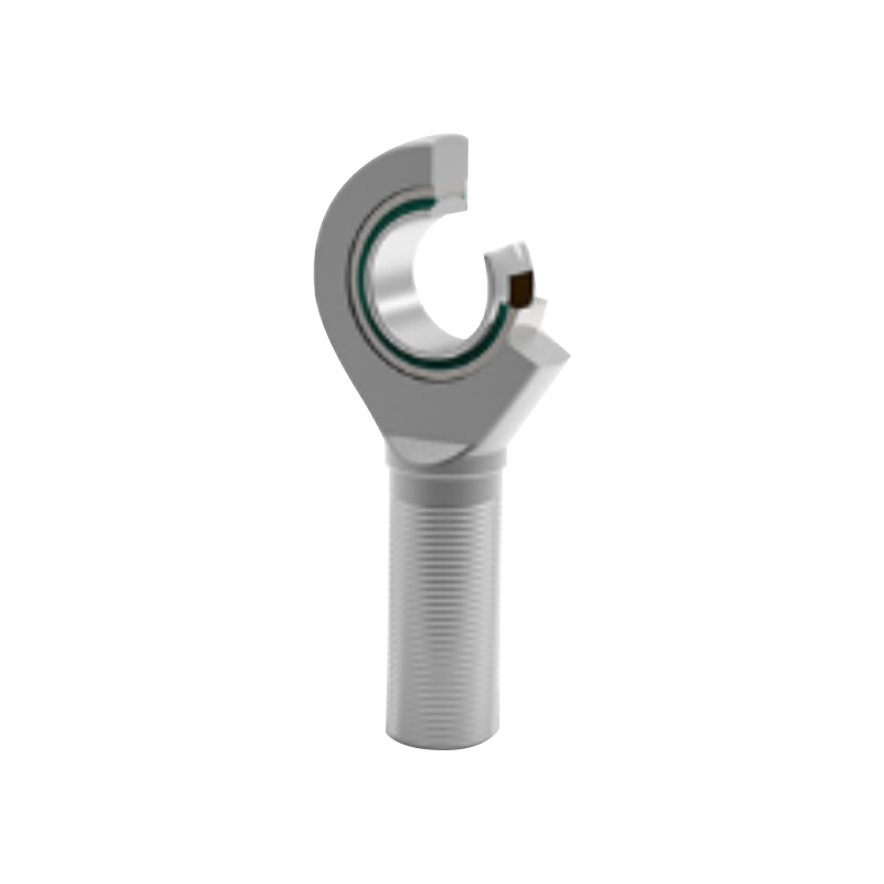
SA Self-Lubricating Rod End Spherical Bearing
The two principal versions are designed to address different size ranges and operating requirements. Selecting the correct version depends on bore diameter, load, movement, environmental conditions, expected operating temperature, and available space.
The SA…C version uses a steel and PTFE composite sliding friction pair. It is available in smaller nominal sizes beginning at approximately 5 mm and extending through approximately 30 mm. This makes it suitable for compact joints, control linkages, light and medium-duty actuators, precision positioning equipment, and general industrial assemblies.
The stated operating temperature range for the SA…C design is approximately 50°C to +150°C. Application temperatures should be assessed carefully because the actual performance of a sliding bearing depends not only on ambient temperature but also on load, speed, oscillation angle, heat dissipation, and the temperature of adjacent components.
The composite construction combines a metallic support structure with a PTFE-based sliding layer. The metal provides load support and dimensional stability, while the PTFE composite contributes low friction and self-lubricating performance. This combination is often preferred when a designer needs a compact bearing with predictable sliding behavior and limited maintenance.
The SA…ETL 2RS version uses a steel and PTFE braided fabric sliding friction pair. It is intended for larger rod end sizes, with the listed range extending from approximately 15 mm to 80 mm. The larger dimensions provide higher load-carrying capability for heavy linkages, structural connections, actuator systems, and industrial machinery.
The stated operating temperature range is approximately 30°C to +130°C. The braided fabric sliding layer is designed to provide a durable bearing interface under radial load and oscillating movement. The 2RS sealing arrangement helps protect the internal bearing area from dust and external contaminants.
The SA…ETL 2RS design can be considered when a larger bearing capacity is needed or when the application benefits from a sealed, self-lubricating arrangement. The selection should still be based on calculated loads rather than size alone. Static loading, dynamic loading, impact, oscillation frequency, and the ratio between radial and axial forces all influence the appropriate model.
| Characteristic | SA…C | SA…ETL 2RS |
|---|---|---|
| Sliding friction pair | Steel/PTFE composite material | Steel/PTFE braided fabric |
| Typical nominal bore range | Approximately 5–30 mm | Approximately 15–80 mm |
| Lubrication requirement | No external lubrication required in normal operation | No external lubrication required in normal operation |
| Stated operating temperature range | Approximately 50°C to +150°C | Approximately 30°C to +130°C |
| Primary design emphasis | Compact, low-friction rod end joints | Larger and higher-capacity sealed rod end joints |
| Typical applications | Control linkages, compact actuators, automation mechanisms | Heavy linkages, larger actuators, industrial machinery |
The table provides a general product comparison. Final selection should be confirmed using the manufacturer’s current dimensional drawings, technical data, and application review, particularly where temperature, impact, contamination, or unusual loads are present.
The SA series includes a wide range of models. The following representative data is derived from the supplied product information. Because technical tables can contain abbreviated designations and size-specific variations, engineers should verify the exact model, thread, dimensions, and load ratings before production use.
| Model | Bore d (mm) | Body width B (mm) | Head diameter dₖ (mm) | Thread | Dynamic load rating (kN) | Static load rating (kN) | Approximate weight (kg) |
|---|---|---|---|---|---|---|---|
| SA5C | 5 | 6 | 10 | M5 | 3.6 | 3.9 | 0.015 |
| SA10C | 10 | 9 | 16 | M10 | 8.6 | 16 | 0.050 |
| SA12C | 12 | 10 | 18 | M12 | 11 | 23 | 0.088 |
| SA15C | 15 | 12 | 22 | M14 | 18 | 32 | 0.120 |
| SA17C | 17 | 14 | 25 | M16 | 22 | 44 | 0.190 |
| SA20C | 20 | 16 | 29 | M20×1.5 | 31 | 60 | 0.300 |
| SA25C | 25 | 20 | 35.5 | M24×2 | 51 | 85 | 0.555 |
| SA30C | 30 | 22 | 40.7 | M30×2 | 65 | 110 | 0.875 |
| SA35ETL 2RS | 35 | 25 | 47 | M36×3 | 140 | 148 | 1.42 |
| SA40ETL 2RS | 40 | 28 | 53 | M39×3 | 175 | 180 | 1.85 |
| SA45ETL 2RS | 45 | 32 | 60 | M42×3 | 225 | 240 | 2.49 |
| SA50ETL 2RS | 50 | 35 | 68 | M45×3 | 275 | 290 | 3.58 |
| SA60ETL 2RS | 60 | 44 | 80 | M52×3 | 430 | 450 | 5.89 |
| SA70ETL 2RS | 70 | 49 | 92 | M56×4 | 550 | 610 | 8.51 |
| SA80ETL 2RS | 80 | 55 | 105 | M64×4 | 705 | 750 | 12.3 |
The supplied data also includes alternative thread and body configurations identified with SAS designations for selected larger sizes. These alternatives can provide different thread dimensions, body lengths, and load characteristics while maintaining the same general self-lubricating concept. Customers requiring a specific SAS configuration should request the relevant drawing and technical data sheet.
Some model entries in the source table contain abbreviated or distorted characters, including designations such as SABC, SABOETL 2RS, and SAS80ETL 2RS. For engineering accuracy, these markings should be treated as provisional until confirmed against the manufacturer’s official drawing. Model identification is particularly important for the 60 mm and 80 mm sizes, where different thread and body configurations may be available.
Every bearing design must be compared according to the application rather than by one isolated feature. The SA series offers several advantages over conventional lubricated rod ends and some general-purpose sliding joint alternatives.
Steel-on-steel rod ends can provide high load capacity, but they typically depend on a continuous supply of grease or oil. In dusty or inaccessible locations, maintaining the lubricant film can be difficult. The SA series avoids routine external lubrication through its PTFE-based sliding materials.
This reduces the need for grease fittings and can improve cleanliness. In food-processing support equipment, packaging machinery, textile machinery, and clean production environments, reducing exposed lubricant may be a major design benefit. The specific suitability of the bearing should still be assessed according to the industry’s hygiene and compliance requirements.
Self-lubricating materials can also provide more consistent friction during short oscillating movements. A grease-lubricated steel-on-steel joint may experience lubricant displacement or uneven distribution when movement is limited. The PTFE sliding interface is integrated into the bearing structure and is therefore less dependent on repeated grease redistribution.
A plain bushing can provide low-friction support, but it does not automatically provide the threaded rod end connection or angular articulation of an assembled spherical bearing. Using a separate bushing, housing, and threaded adapter may require more components and more installation space.
The SA bearing integrates these functions into one compact unit. This can reduce assembly complexity and limit the number of interfaces that must be aligned. The spherical geometry also provides angular movement that a standard cylindrical bushing cannot provide without additional articulation features.
Many rod end bearings on the market are designed for a narrow range of dimensions or rely on fixed standard configurations. The SA product family provides multiple sizes, thread pitches, thread directions, and body arrangements. This gives machinery designers greater flexibility when adapting the bearing to a new mechanism or replacing an existing component.
UKL’s integrated manufacturing and trading capability also supports OEM and ODM requirements. Instead of selecting only from an existing catalog, customers can discuss dimensional requirements, special thread precision, left-hand thread options, packaging, and production quantities with a supplier that manages engineering and international distribution together.
Low-cost rod ends may appear attractive at the purchasing stage but can create hidden costs through inconsistent dimensions, uncertain material quality, premature wear, and irregular availability. A reliable bearing must perform consistently across batches and remain compatible with the original equipment design.
A manufacturer with defined production processes, inspection procedures, traceability practices, and technical support can provide greater confidence than an unverified source. The value of the SA series is therefore not limited to the product’s material construction. It also includes the manufacturing organization, application support, and ability to supply repeat orders.
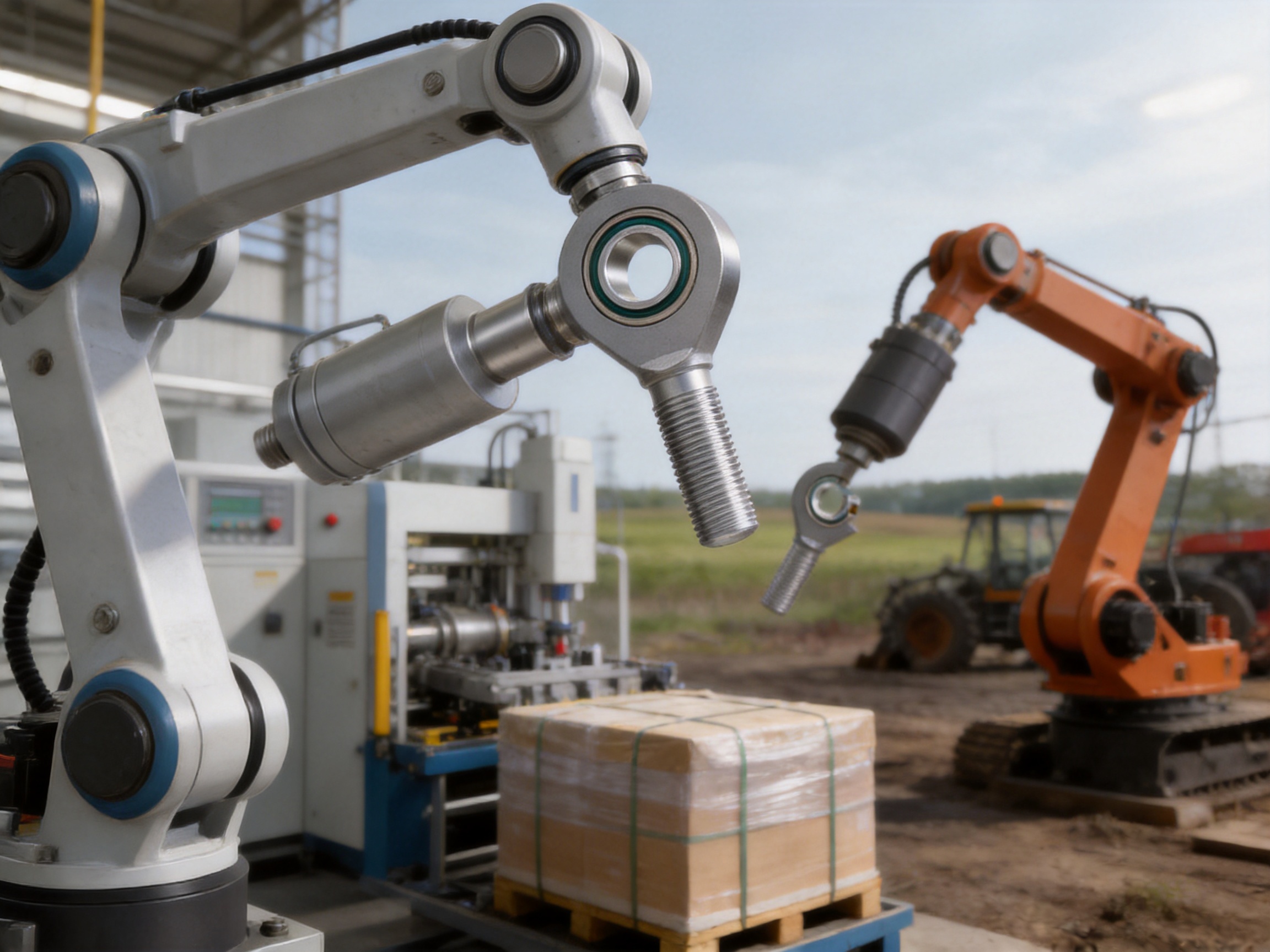
Automated equipment uses many articulated joints to transfer motion from motors, cylinders, cams, and linear guides. Rod end spherical bearings can connect actuators to levers, guide mechanisms, grippers, and positioning arms. Their angular compensation helps maintain smooth movement when the actuator and driven mechanism change relative position during a stroke.
The self-lubricating construction is useful in automated equipment because service intervals are often scheduled around production demands. Reducing lubrication points can help shorten maintenance stops and prevent grease from reaching sensors, belts, products, or protective covers.
Robotic mechanisms require compact joints with predictable movement and low maintenance. The SA series can be used in selected auxiliary joints, linkages, end-effector mechanisms, articulated supports, and motion-transfer assemblies. The correct model depends on the robot’s load spectrum, acceleration, duty cycle, oscillation angle, and accuracy requirements.
Robotic systems may operate through millions of repeated cycles. A suitable rod end must therefore be evaluated under actual motion conditions rather than static load alone. The manufacturer can assist with model selection when customers provide speed, load, angle, frequency, and expected service life information.
Rod end spherical bearings are commonly used at the ends of pneumatic and hydraulic cylinders. The joint allows the cylinder to push or pull a mechanism even when the mounting points do not remain perfectly collinear. This reduces side loading on the cylinder rod and helps the mechanism follow its intended path.
In cylinder applications, the rod end should be installed so that the primary load is carried through the spherical center. Excessive side thrust, bending, shock, or over-tightening can damage the joint or shorten the life of the cylinder assembly. Proper alignment and adequate thread engagement are essential.
Packaging machines often contain fast-moving linkages and repeated reciprocating motions. A self-lubricating rod end can support indexing arms, sealing mechanisms, cutting assemblies, transfer devices, and guide linkages. The absence of routine grease application can help maintain a cleaner working environment and reduce the likelihood of lubricant transfer to packaging materials.
Material-handling systems also benefit from compact, adjustable connections. The available thread configurations allow designers to use rod ends in tensioning and alignment mechanisms where the distance between two components must be fine-tuned during installation.
Agricultural and construction equipment often operates under vibration, dust, shock, and outdoor exposure. Rod end spherical bearings may be used in control linkages, hydraulic attachments, leveling systems, steering mechanisms, and adjustable support assemblies.
For these applications, environmental protection and load assessment are especially important. The galvanized surface provides general corrosion resistance, but severe mud, water immersion, chemicals, or abrasive contamination may require additional protective measures. Sealed SA…ETL 2RS configurations can be considered where the larger size and sealing arrangement are suitable.
Transportation equipment uses articulated joints in suspension components, control systems, seat mechanisms, door systems, and adjustable linkages. The spherical rod end can accommodate angular changes caused by movement and vibration while maintaining a compact connection.
Vehicle applications often involve dynamic loads and safety-critical requirements. The bearing should be selected only after considering the relevant design standards, fatigue conditions, impact loads, temperature range, corrosion exposure, and required inspection intervals.
The performance of a rod end spherical bearing depends on more than its nominal dimensions. Material consistency, machining accuracy, heat treatment, surface quality, assembly precision, and inspection discipline all contribute to product reliability. UKL Bearing Manufacturing Co., Ltd. integrates research and development, production, and international distribution to support these requirements.
The company operates production lines covering forging, turning, heat treatment, grinding, assembly, and packaging. Managing these steps within an integrated manufacturing system can improve process coordination and reduce dependence on disconnected suppliers.
Forging can provide a strong starting form for suitable metal components. Turning establishes the principal external geometry and thread-related features. Heat treatment can be used to obtain the required material properties. Grinding improves dimensional accuracy and surface finish where close tolerances are needed. Assembly combines the rod end body and spherical bearing into a functional unit, while packaging protects the product during storage and transportation.
Each process must be controlled according to the component’s function. The rod end body requires stable geometry and adequate thread strength. The spherical bearing requires accurate spherical contact, suitable surface conditions, and correct retention within the housing. The finished assembly must provide the designed movement without excessive looseness or binding.
UKL maintains an R&D focus on high-precision bearings, including cross roller bearings, dual-direction thrust angular contact ball bearings, and other products used in CNC machines, robotics, and intelligent automation. This engineering background is relevant to rod end development because modern motion systems increasingly demand compact dimensions, repeatable movement, low maintenance, and consistent quality.
Research and development also supports customization. Customers may require a special thread pitch, left-hand thread, modified length, different installation geometry, or a particular packaging arrangement. An engineering-oriented manufacturer can evaluate whether the requested changes are compatible with load, strength, assembly, and production requirements.
Digital production control can help manufacturers monitor process information, coordinate production orders, and maintain consistency across multiple batches. For bearing products, process control is important because small changes in dimensions or surface conditions can affect fit, friction, alignment, and service life.
Production control should be supported by appropriate inspection at incoming material, in-process, and final stages. Typical checks may include dimensional inspection, thread verification, surface inspection, assembly checks, visual examination, and load or movement evaluation according to the product and customer requirements.
UKL reports a production capacity of approximately 10,000 to 50,000 units per month and more than 15 years of OEM and ODM export experience. This capacity can support both regular catalog orders and larger industrial programs. The company serves customers in Europe, Asia, Africa, Russia, the United States, Italy, Germany, Poland, South Africa, Egypt, India, and other markets.
International supply requires more than manufacturing capacity. It requires communication, documentation, packaging coordination, delivery planning, and after-sales support. UKL’s multilingual service team provides technical response, installation guidance, and maintenance support for customers in different regions.
For a rod end bearing, consistency is essential. The thread must match the mating component, the spherical center must remain correctly positioned, and the sliding interface must provide stable movement. Variations in assembly or material quality may lead to unwanted play, installation difficulty, or premature wear.
A structured manufacturing process helps reduce these risks. The combination of forging, machining, heat treatment, grinding, assembly, and packaging allows each production stage to contribute to the finished product’s quality. Customers requiring formal inspection records, sampling plans, or special quality documentation should discuss these requirements before placing an order.
Correct installation is necessary to obtain the expected performance of any rod end spherical bearing. Before installation, verify the model, bore diameter, thread type, thread direction, body dimensions, and load orientation. Confirm that the mating shaft or pin is compatible with the spherical bearing and does not have excessive roughness, burrs, or dimensional variation.
The mating shaft should be aligned with the spherical center. Do not force the shaft into the bearing at an angle or use impact tools directly on the bearing surfaces. If a press fit or retaining arrangement is required, the installation method should be designed so that force is applied to the appropriate component rather than through the sliding layer.
Thread engagement should be sufficient for the expected load. Avoid using a thread engagement length that is too short, especially in high-load or shock-loaded applications. At the same time, the rod end should not be installed in a way that creates interference with the spherical head, adjacent structure, or moving linkage.
Use suitable locking methods where vibration or cyclic loading may loosen the threaded connection. Depending on the application, this may include a locknut, mechanical locking feature, thread-locking compound, or a designed clamping arrangement. The selected method must be compatible with the operating temperature and maintenance requirements.
Do not rotate or adjust the rod end by applying excessive torque directly to the spherical bearing. Use the designated flats or appropriate installation surfaces on the rod end body. Excessive installation torque can distort the housing or damage the thread.
After installation, move the mechanism slowly through its complete range. Check for binding, interference, excessive resistance, abnormal noise, or restricted angular movement. Verify that the joint does not reach its angular limit during normal operation unless the design specifically allows it.
The dynamic load rating is used as a reference for moving or oscillating conditions, while the static load rating relates to load-carrying capacity when the bearing is stationary or subjected to limited movement. These values should not be interpreted as universal permissible loads for every application.
Actual allowable load depends on load direction, oscillation angle, frequency, speed, impact, temperature, shaft material, surface hardness, alignment, and expected service life. A bearing that is suitable under a steady radial load may not be suitable under a high-frequency reversing load or repeated shock.
Rod end spherical bearings are often used in oscillating mechanisms. The smaller the oscillation angle, the more important it becomes to consider localized contact and wear behavior. The frequency of movement also influences heat generation and material fatigue.
Designers should provide the manufacturer with the expected angular range, cycles per minute, operating hours per day, and total target life. This information allows a more meaningful evaluation than a simple comparison of nominal load ratings.
Although radial load is usually the primary design consideration, many rod ends experience a combination of radial, axial, and moment loads. A misaligned connection may also generate secondary bending forces in the threaded shank. The bearing should be arranged so that the main force passes through the spherical center whenever possible.
If a high moment load is unavoidable, a larger rod end or an alternative joint arrangement may be required. In critical designs, finite element analysis, prototype testing, or application-specific validation may be appropriate.
The stated temperature range for the SA…C version is approximately 50°C to +150°C, while the SA…ETL 2RS version is approximately 30°C to +130°C. These figures provide a general reference, but temperature effects must be reviewed together with load and movement.
High temperature can affect the polymeric sliding material, dimensional stability, friction, and the strength of surrounding components. Low temperature can influence material flexibility and starting friction. If the bearing is installed near a heat source or in a refrigerated environment, the actual temperature at the sliding interface should be considered.
Dust, abrasive particles, water, chemicals, and metal chips can reduce the service life of any sliding bearing. The sealed 2RS configuration provides additional protection, but it should not be treated as unlimited protection against immersion or severe contamination.
Where possible, install the rod end away from direct contamination sources. Use shields or guards when the mechanism operates near abrasive dust or cutting debris. During maintenance, inspect the surrounding structure and remove contaminants without forcing debris into the spherical interface.
The self-lubricating design eliminates routine grease replenishment in normal conditions, but inspection remains necessary. Maintenance personnel should periodically check the threaded connection, body surface, spherical movement, seals where applicable, and surrounding components.
Signs of possible wear include increased clearance, unusual noise, rough movement, visible damage to the spherical surface, thread deformation, corrosion, or a change in the mechanism’s position under load. Any rod end that develops excessive play or cracking should be removed from service and replaced.
Inspection frequency should be based on duty cycle and risk. A lightly loaded indoor linkage may require less frequent inspection than a high-cycle robotic mechanism or an outdoor construction machine. Safety-related applications should have documented inspection criteria and replacement limits.
Do not attempt to restore a worn self-lubricating bearing by injecting grease unless specifically instructed by the manufacturer. External grease may not improve the internal sliding interface and can attract contaminants. If friction or wear becomes abnormal, investigate alignment, load, contamination, temperature, and installation conditions.
Rod end bearing requirements frequently differ from standard catalog dimensions. A machine builder may need a special thread pitch, left-hand thread, customized thread precision, modified body length, alternative installation dimensions, private labeling, or a packaging specification suitable for a global supply chain.
UKL indicates that rod end bearings with different pitches or special thread precision requirements are available. The left-hand thread marking system provides a clear method for identifying special thread direction. Customers should submit a technical drawing or complete dimensional requirement when requesting a customized product.
For OEM projects, the most useful information includes nominal bore diameter, thread specification, thread direction, overall length, head diameter, body width, expected radial and axial loads, angular movement, speed or frequency, operating temperature, contamination conditions, required quantity, and target service life.
Prototype and sample evaluation can be used to confirm fit and movement before full production. For large projects, customers may also request inspection documents, production samples, packaging tests, or batch identification arrangements. Early communication helps avoid costly changes after tooling or production planning has begun.
Choosing a bearing supplier involves more than comparing unit prices. A manufacturer with integrated production and engineering resources can provide better control over design changes, production scheduling, quality feedback, and technical communication.
UKL combines manufacturing and international trading functions. Its product range supports multiple bearing categories, allowing customers to consolidate sourcing for different machine assemblies. This can simplify vendor management and create greater consistency across related products.
The company’s reported workforce of 201 to 500 employees and its production capacity of 10,000 to 50,000 units per month indicate an organization capable of supporting both standard and project-based supply. Its export experience across Europe, Asia, Africa, Russia, North America, and other markets provides familiarity with international shipping, customer communication, and industrial procurement requirements.
The company also emphasizes sustainability through environmentally responsible processes, material recycling, and energy optimization. Although sustainability performance should be evaluated using project-specific documentation when required, these practices reflect the importance of considering environmental impact throughout manufacturing and distribution.
For customers purchasing rod end bearings, the main advantage of an integrated supplier is continuity. The same organization can discuss product design, manufacturing feasibility, inspection, packaging, shipment, and after-sales support. This can be especially valuable for equipment builders that require repeatability over several years of production.
The first selection parameter is the bore diameter. The bore must match the mating shaft or pin while allowing the required fit and movement. A bore that is too small cannot be assembled, while an excessively large bore may create unwanted clearance and impact.
The second parameter is the load. Compare the calculated application load with the dynamic and static ratings, while applying appropriate safety factors. Consider peak loads rather than only average loads. If the mechanism experiences shock or sudden reversal, the peak value may control the selection.
The third parameter is the thread. Confirm nominal diameter, pitch, tolerance, thread direction, and available engagement length. If adjustment is required, determine whether a right-hand or left-hand thread is appropriate.
The fourth parameter is the operating environment. Review temperature, dust, moisture, chemicals, vibration, and accessibility for maintenance. The SA…C and SA…ETL 2RS variants have different material systems and temperature ranges, so the environment may influence the choice.
The fifth parameter is movement. Identify whether the bearing will experience continuous rotation, limited oscillation, reciprocating movement, or occasional articulation. Note the angular range, speed, frequency, and cycle count.
The sixth parameter is installation space. Check the head diameter, body width, overall length, thread length, minimum installation lengths, and angular clearance. A bearing that meets the load requirement may still be unsuitable if its head or body interferes with surrounding parts.
| Selection question | Required information |
|---|---|
| What shaft or pin will be used? | Bore diameter, fit, surface condition, hardness, and retention method |
| What load will be applied? | Radial load, axial load, peak load, impact, and safety factor |
| How will the bearing move? | Rotation, oscillation angle, frequency, speed, and duty cycle |
| What thread is needed? | Diameter, pitch, direction, tolerance, engagement length, and adjustment method |
| What is the environment? | Temperature, dust, water, chemicals, vibration, and outdoor exposure |
| What are the space limits? | Head diameter, body width, length, clearance, and mounting orientation |
| What support is required? | Samples, drawings, inspection documents, packaging, and delivery schedule |
When requesting a quotation, specify the complete model rather than only the nominal bore. For example, a request should identify whether the requirement is SA20C, SA20ETL 2RS, or a customized alternative. Include the thread specification and thread direction, especially for adjustable or paired mechanisms.
Provide the intended quantity and forecast if the product will be used in a continuing program. This allows the manufacturer to plan production capacity, packaging, and potential tooling requirements. For OEM applications, an annual demand estimate is helpful even when the initial order is small.
Request a current drawing when the product table contains unclear or abbreviated data. This is particularly important for larger sizes and alternative SAS configurations. Confirm dimensions in millimeters, load-rating units, thread notation, and weight before releasing the bearing into production.
For applications involving safety, high temperature, high impact, or long service life, provide operating details to the manufacturer’s technical team. A generic catalog selection may not be sufficient for a specialized machine. Application review can help identify whether a self-lubricating rod end is suitable or whether another bearing arrangement is better.

It means that the sliding friction pair is designed to operate without routine external grease or oil application under normal conditions. The SA…C version uses steel and PTFE composite material, while the SA…ETL 2RS version uses steel and PTFE braided fabric. The bearing should still be protected from severe contamination and operated within its specified conditions.
Rod end spherical bearings are primarily intended for oscillating, articulating, or limited rotational movement. Continuous rotation may be possible in some applications, but it must be evaluated according to speed, load, temperature, shaft condition, and lubrication material. Customers should consult the manufacturer before using the bearing for continuous high-speed rotation.
SA…C uses a steel/PTFE composite sliding pair and is generally available in smaller sizes. SA…ETL 2RS uses a steel/PTFE braided fabric sliding pair and is generally available in larger sizes with a sealed arrangement. Their stated operating temperature ranges also differ, so the application conditions should be reviewed before selection.
No. Galvanizing provides general corrosion protection, but severe moisture, salt, chemicals, mud, immersion, and abrasive contamination can exceed the intended conditions. Outdoor applications should be reviewed according to the actual environment, and additional shielding or a different surface treatment may be required.
Yes. The supplied product information states that left-hand thread versions are available. The model and thread marking should include “L” and “left,” such as SAL20C M20×1.5 left 6g. The thread direction should be clearly stated in purchase documents and drawings.
Routine external grease is not required for normal operation of the self-lubricating sliding pair. Adding grease without technical guidance may attract dust or create contamination. If the bearing operates under unusual conditions, consult the manufacturer rather than changing the lubrication method independently.
Match the bore to the correct shaft or pin, ensure adequate thread engagement, use suitable locking methods, avoid impact on the spherical bearing, and verify free angular movement after installation. The load should pass as close as possible through the spherical center, and the mechanism should not exceed the permitted angular movement.
Important information includes bore diameter, thread size and pitch, thread direction, radial and axial loads, peak impact load, angular movement, operating frequency, temperature, contamination, available space, and desired service life. Providing these details enables a more reliable technical recommendation.
The supplied information states that different pitches and special thread precision requirements are available. OEM and ODM support is also part of the company’s business capability. Customized requirements should be submitted with a drawing or complete specification for technical review.
No. Dynamic and static ratings are reference values and should not automatically be treated as permissible loads in every application. Actual allowable loading depends on movement, impact, alignment, temperature, shaft condition, and required service life. A qualified engineer should review critical applications.
Inspect the threaded connection, body surface, spherical movement, seals, clearance, corrosion, and surrounding structure. Look for unusual noise, rough movement, visible damage, excessive play, or changes in alignment. Replace the bearing if wear or damage exceeds the application’s acceptable limit.
Some supplied entries contain abbreviated or unclear model markings and may represent alternative configurations. A current manufacturer drawing should be used to confirm exact model names, dimensions, thread specifications, load ratings, and weights, particularly for larger SA and SAS versions.
Consider a pneumatic actuator connected to a pivoting machine arm. During the actuator stroke, the distance and angle between the cylinder rod and the arm change continuously. If a rigid threaded connection is used, the cylinder rod may experience bending or side loading. A rod end spherical bearing can allow the connection to articulate while the actuator continues to transmit axial force.
If the application is located inside a clean automated production line and requires frequent cycles, the self-lubricating construction may reduce maintenance interruptions. The designer would first determine the maximum actuator force, the rod diameter, the angular movement, the stroke frequency, and the available installation space.
The next step would be to compare the calculated force with the relevant dynamic and static ratings. The designer would then select a thread size that provides adequate engagement and determine whether a right-hand or left-hand thread is required for adjustment. Finally, the complete mechanism would be tested for interference, angular clearance, and abnormal load transfer.
This example demonstrates why selecting a rod end based only on bore diameter is insufficient. The bearing must be treated as part of the entire linkage. Correct alignment, load direction, thread engagement, and operating cycle determine whether the selected model will deliver a satisfactory service life.
The value of a self-lubricating rod end bearing is measured through the complete operating life of the equipment. A component that reduces maintenance, simplifies installation, and maintains consistent motion can contribute to lower operating costs even when its initial purchase price is not the lowest available.
For equipment builders, standardizing on a dependable product family can simplify design libraries, spare-parts management, and production training. The broad SA range allows different machine sizes to use the same general bearing concept while selecting an appropriate bore, thread, body geometry, and load rating.
For distributors, a product family with multiple sizes and variants creates opportunities to support customers across different industries. Reliable technical documentation, model identification, packaging consistency, and international communication are important factors in building repeat business.
For end users, the principal benefits are reduced lubrication work, compact articulation, and improved flexibility in equipment design. When properly selected and installed, the SA series can provide a practical connection solution for many reciprocating and oscillating mechanisms.
The SA self-lubricating rod end spherical bearing combines a galvanized carbon steel rod end body with a self-lubricating radial spherical bearing. Its steel/PTFE composite and steel/PTFE braided fabric friction pairs are designed to provide low-maintenance sliding performance without routine external lubrication. The spherical construction accommodates angular misalignment, while the threaded body provides a compact and adjustable connection for industrial mechanisms.
The product family offers important advantages over conventional lubricated rod ends, separate bushing arrangements, and uncontrolled low-cost alternatives. These advantages include reduced maintenance, smooth oscillating movement, compact integration, broad size availability, corrosion-resistant surface treatment, and options for special thread pitches and left-hand threads.
UKL Bearing Manufacturing Co., Ltd. strengthens the product offering through integrated production capabilities covering forging, turning, heat treatment, grinding, assembly, and packaging. Its R&D resources, OEM and ODM experience, international distribution network, and technical service support allow the company to serve both standard catalog requirements and customized industrial projects.
Successful application depends on correct selection. Engineers should evaluate bore size, thread specification, dynamic and static loads, angular movement, temperature, contamination, installation space, and expected service life. Current drawings and technical confirmation should be obtained for unclear or customized models.
For automation, robotics, actuators, packaging machinery, agricultural equipment, construction machinery, transportation systems, and general industrial linkages, the SA self-lubricating rod end spherical bearing provides a durable and efficient foundation for articulated motion. Its combination of self-lubricating materials, compact design, manufacturing capability, and customization support makes it a strong option for modern equipment requiring reliable, low-maintenance joints.
1. UKL Bearing Manufacturing Co., Ltd., SA Self-Lubricating Rod End Spherical Bearing Product Information.
2. UKL Bearing Manufacturing Co., Ltd., Product Dimensions and Load Rating Table for SA and SAS Rod End Bearings.
3. General engineering principles for spherical plain bearings, rod end bearings, and oscillating sliding contacts.
4. General design practice for industrial bearing installation, alignment, load evaluation, and maintenance.
5. General materials engineering references concerning PTFE composite and PTFE braided fabric sliding friction pairs.
6. General manufacturing references concerning forging, turning, heat treatment, grinding, assembly, and dimensional inspection of bearing components.
Product Categories
Contact Us

Jane@ukl-bearing.com
Jenny@ukl-bearing.com
Andy@ukl-bearing.com
Ivy@ukl-bearing.com

+86-510- 88763239
+86-15371057968

No.1 Hehuan Road, Hudai Town, Binhu District, Wuxi City.
Ready to Begin?
Get in Touch

Now!
UKL BEARING
 English
 Español
 русский