Content
Modern manufacturing depends on rotary motion that is not only smooth and reliable, but also measurable, controllable, and repeatable. In high-precision CNC machine tools, rotary tables, machining centers, industrial robots, radar systems, aerospace equipment, and scientific instruments, even a very small angular deviation can affect the quality of the finished product. As tolerances become tighter and production systems become more automated, manufacturers need bearing assemblies that can support heavy loads while also providing dependable angular-position feedback.
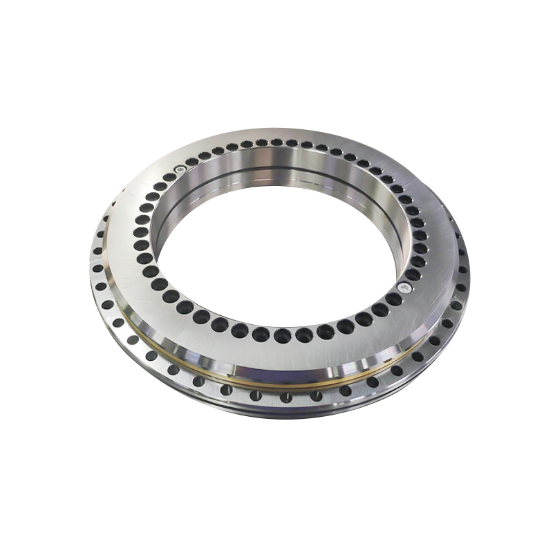
The YRTM angle measurement bearing is designed for this purpose. It combines the structural functions of a precision rotary table bearing with an integrated non-contact inductive angle measurement system. This arrangement allows the bearing to support axial loads, radial loads, and overturning moments while simultaneously measuring rotary displacement. The result is a compact and highly integrated solution for applications in which bearing accuracy and angular measurement accuracy must work together.
Instead of installing a separate bearing, encoder, mounting structure, and correction system, equipment designers can use one coordinated assembly. This can reduce the space required inside the machine, simplify installation, shorten alignment procedures, and improve the relationship between the bearing’s actual rotation and the signal used by the control system.
Rotary tables and precision rotary axes are used to position workpieces, tools, sensors, antennas, and robotic components. In each case, the control system must know the actual angular position of the rotating component. A commanded position is not always the same as the position achieved under load. Bearing radial deviation, thermal expansion, mounting errors, structural deformation, and external vibration can all influence the final position.
A conventional rotary system may use a precision bearing together with an optical encoder or magnetic encoder. Although these arrangements can provide excellent results, they often require additional installation space and careful alignment between the bearing axis and the encoder scale. The encoder may measure the position of a separate component rather than directly reflecting the behavior of the bearing. If the bearing and encoder experience different mechanical deviations, the control system may not detect all of the errors that influence the workpiece.
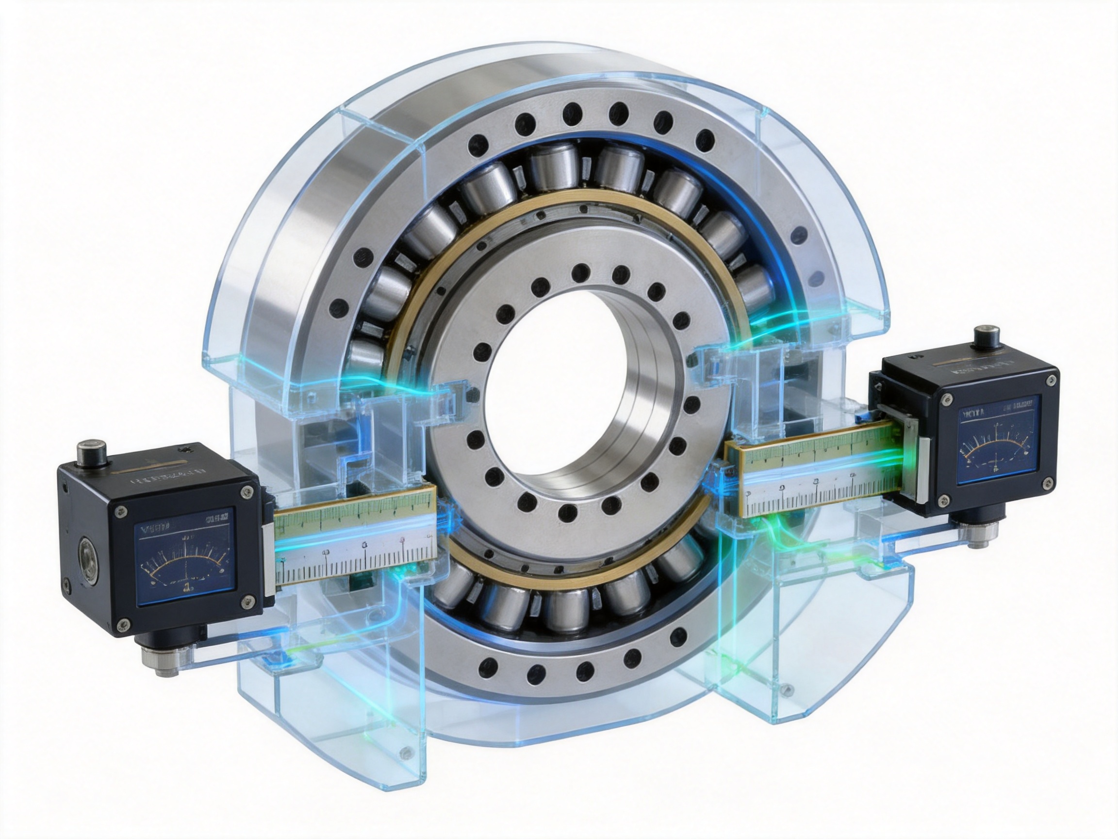
The YRTM design places the angle measurement system within the rotary bearing assembly. A dual-reading-head arrangement can detect and compensate for radial deviations in real time. This is important because a single reading head may interpret eccentricity or radial run-out as an angular-position error. Two reading heads provide additional information about the position of the measurement element and allow the system to distinguish actual angular movement from certain radial deviations.
This approach is especially valuable in CNC rotary tables, where a small angular error may result in contour inaccuracies, poor surface finish, incorrect hole positioning, or errors during multi-axis interpolation. It is also useful in robotic joints and precision positioning systems, where repeatability, dynamic response, and compact construction are essential.
The YRTM angle measurement bearing is based on the geometry of a high-precision rotary table bearing. Its internal rolling elements and raceways are arranged to provide high axial stiffness, radial support, and resistance to overturning moments. The bearing is designed to maintain stable rotation while carrying combined loads from the machine structure or workpiece.
The measurement section uses a non-contact inductive encoder principle. Unlike a contacting sensor, the inductive system does not require a mechanical sliding element to read the angular scale. The absence of direct contact eliminates wear at the sensing interface and supports long-term signal stability when the bearing is properly installed and operated.
During rotation, the measurement element produces an electrical signal corresponding to angular displacement. Depending on the selected output configuration, the signal can be supplied as a sine wave signal, commonly identified as 1 Vpp, or as a square-wave TTL signal. These formats are suitable for integration with industrial motion controllers and CNC systems. The supplied information identifies compatibility with Siemens and FANUC CNC systems, which are widely used in machine-tool applications.
The dual-reading-head configuration further improves measurement reliability. The reading heads are positioned to observe the measurement element from different points. By comparing the signals, the system can compensate for certain radial deviations and improve the relationship between measured angle and actual bearing rotation. This is a significant advantage in a bearing-mounted measurement system because the bearing itself is the mechanical reference for the rotary axis.
The measurement system is enclosed in a compact construction intended to resist industrial contamination. The stated IP67 protection rating indicates protection against dust ingress and temporary immersion under defined test conditions. Actual protection depends on correct installation, cable routing, sealing, connector selection, and compliance with the manufacturer’s installation instructions. Nevertheless, the sealed design provides an important advantage over exposed measurement arrangements in environments containing oil mist, coolant, dust, or solid particles.
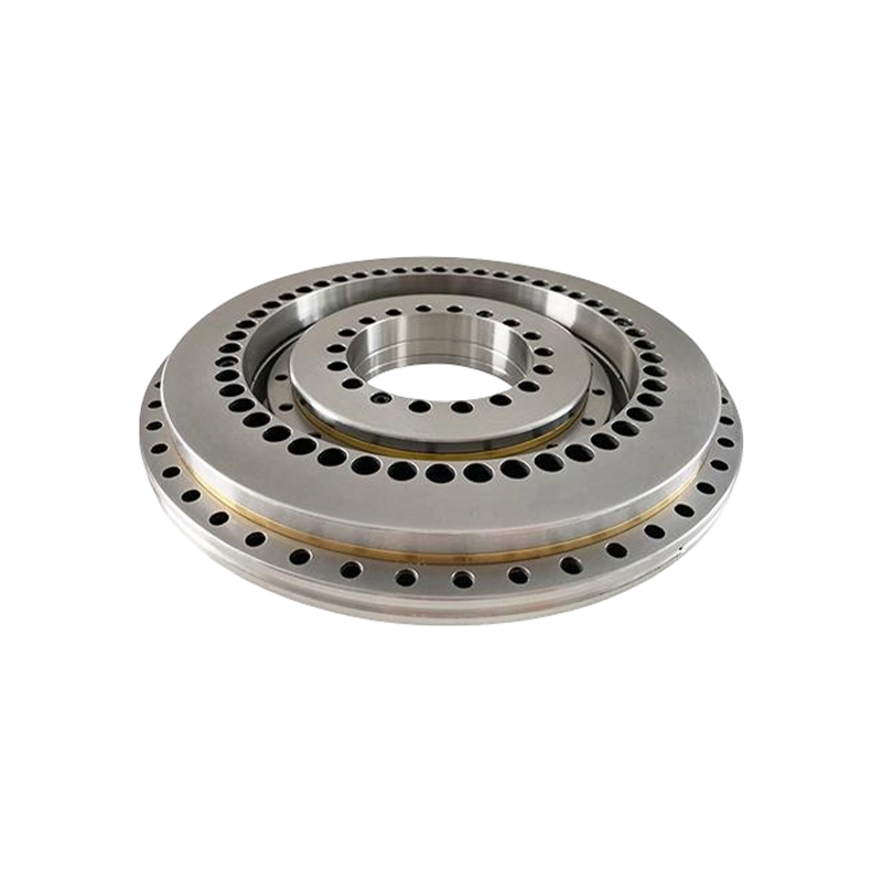
YRTM Angle Measurement Bearing
The most fundamental advantage of the inductive measurement system is that it operates without mechanical contact between the sensor and the measured scale. Optical systems may also use non-contact reading, but the YRTM inductive arrangement does not depend on optical clarity between a light source and a photodetector. This makes the measurement principle less sensitive to certain forms of contamination, including oil, dust, and solid particles.
Because there is no contacting sensing component, there is no frictional wear at the measurement interface. This supports long service life and reduces the possibility that sensor wear will gradually change the output signal. The bearing’s rolling elements and raceways still require appropriate lubrication, preload control, and maintenance, but the angle measurement element itself is designed for wear-free operation.
The product information specifies angular measurement accuracy of up to 2 arcseconds for the YRTM series and identifies a maximum accuracy value of 23 in the description of the steel-grid measurement system. These figures should be confirmed against the exact model, measurement configuration, installation conditions, and technical drawing before final equipment design. Even with this qualification, the stated performance places the product in the class of precision measurement solutions intended for demanding rotary applications.
In practical use, measurement accuracy is influenced by more than the encoder itself. Bearing run-out, mounting flatness, shaft and housing stiffness, thermal behavior, cable installation, controller interpolation, and environmental vibration can all affect system-level accuracy. The YRTM design addresses this challenge by combining the bearing and measurement system in a coordinated assembly. This gives equipment builders a more direct path toward achieving high angular accuracy than using loosely integrated components.
The dual-reading-head system is one of the product’s principal differentiating features. Radial deviation in a rotary bearing can create a measurement error if the encoder reads only from one point. By comparing two signals, the system can identify changes associated with bearing radial movement and perform real-time correction.
This function is particularly beneficial for large-diameter rotary tables and heavily loaded axes. As workpiece weight, cutting forces, or overturning moments change, the bearing may experience small elastic or geometric deviations. A measurement system with radial-deviation correction can provide more reliable feedback under these changing conditions.
Real-time correction does not eliminate the need for accurate mounting or appropriate bearing selection. It is not a substitute for a rigid machine structure, correct preload, or proper alignment. Instead, it adds an additional layer of compensation that can improve the usable accuracy of the complete rotary axis.
Precision rotary axes are not always operated slowly. Modern machining centers may use high-speed positioning, rapid indexing, and complex interpolated motion. Robotic systems may also need quick response during repeated cycles. The YRTM measurement system is designed for high speed, high dynamic performance, and high resolution.
Accurate feedback at higher rotational speeds allows the controller to respond quickly to changes in position. This can improve positioning behavior, reduce settling time, and support more efficient production cycles. The bearing’s load-carrying design also allows the rotary assembly to maintain stability during acceleration, deceleration, and reversing motion.
Speed capability varies by model. The supplied technical data lists grease-lubricated limiting speeds from approximately 120 r/min to 280 r/min for the listed YRTM150 through YRTM460 sizes. The correct operating speed must be evaluated together with load, duty cycle, lubrication, temperature, mounting stiffness, and permissible vibration.
The measurement system contains no magnetic components and does not depend on magnetic tape. This avoids concerns associated with magnetic hysteresis, magnetic response, and demagnetization. In areas containing motors, electromagnetic actuators, power electronics, or other magnetic fields, the absence of magnetic sensing components can simplify system integration.
Optical and magnetic encoders each have useful application areas, but the best choice depends on the environment and design priorities. An inductive system offers a practical alternative when the equipment builder wants high resolution without magnetic components and with greater tolerance of industrial contamination than an exposed optical scale may provide.
Space is often limited inside machine-tool rotary tables, robot joints, and inspection equipment. A separate bearing and encoder can require additional axial or radial room, special mounting brackets, and access for alignment. The integrated YRTM assembly addresses this limitation by incorporating the angle measurement system into the bearing structure.
The compact design can simplify the mechanical layout. It may allow the rotary table to remain lower in height, create more space for workholding components, or reduce the size of a robot joint. It can also reduce the number of interfaces between the mechanical and electrical systems. Fewer interfaces generally make it easier to establish a consistent reference between the bearing, the encoder, and the machine controller.
Machine tools commonly operate with cutting fluid, lubricating oil, chips, metal dust, and cleaning procedures. Industrial robots may operate in dusty production areas or near welding and material-handling processes. A measurement system that is insensitive to many forms of dirt can provide a valuable reliability margin.
The stated IP67 protection rating is designed for resistance to dust and certain water exposure. The protection level should be maintained by using suitable connectors, cable glands, seals, and mounting practices. The bearing should not be treated as universally immune to every chemical, temperature, pressure, or cleaning method. A project-specific environmental review remains necessary, particularly when the application involves high-pressure coolant, corrosive chemicals, abrasive particles, or extreme temperatures.
The ability to output either a 1 Vpp sine-wave signal or a TTL square-wave signal supports integration with different CNC and motion-control architectures. A sine-wave output can be useful when the control system performs interpolation for high-resolution position information. TTL output may be preferred when the controller is configured for digital pulse processing.
Signal selection should be made during the design stage. The engineering team should confirm the controller’s input type, signal amplitude, cable length, shielding requirements, grounding method, interpolation capability, maximum input frequency, and connector arrangement. Correct signal integration is essential for realizing the accuracy of the mechanical bearing and encoder combination.
The YRTM series covers several large-diameter rotary bearing sizes. The listed models range from YRTM150 to YRTM460. The first number in each designation corresponds to the nominal bore diameter in millimeters. The series therefore supports different rotary-table sizes, workpiece capacities, and machine architectures.
| Model | Bore d (mm) | Outside Diameter D (mm) | Height H (mm) | Approximate Weight (kg) | Grease-Lubricated Limiting Speed (r/min) |
|---|---|---|---|---|---|
| YRTM150 | 150 | 240 | 43 | 10 | 320 |
| YRTM180 | 180 | 280 | 46 | 12 | 280 |
| YRTM200 | 200 | 300 | 47 | 14 | 260 |
| YRTM260 | 260 | 385 | 55 | 20 | 200 |
| YRTM325 | 325 | 450 | 60 | 40 | 170 |
| YRTM395 | 395 | 525 | 65 | 55 | 140 |
| YRTM460 | 460 | 600 | 70 | 70 | 120 |
The dimensions and performance data should be used as preliminary selection information. The final model should be chosen after reviewing the required bore, outside diameter, installation height, fixing-hole arrangement, axial load, radial load, overturning moment, speed, friction moment, stiffness, and measurement interface.
For example, the YRTM150 has a nominal 150 mm bore, a 240 mm outside diameter, and an approximate weight of 10 kg. The YRTM460 increases the nominal bore to 460 mm and the outside diameter to 600 mm, with an approximate weight of 70 kg. The larger model provides a substantially larger working envelope, but its speed rating is lower and its installation structure must be designed to support the increased mass and load capacity.
The listed dynamic axial load capacity rises from approximately 56 kN for the YRTM150 to approximately 200 kN for the YRTM460. Static axial capacity rises from approximately 170 kN to approximately 765 kN across the same range. These figures demonstrate the series’ ability to address applications involving substantial axial forces. However, load capacity is not the only selection criterion. The operating moment, load distribution, preload, speed, and stiffness requirements must also be assessed.
A rotary table bearing must do more than guide rotation. It must resist forces acting in several directions and maintain the relative position of the rotating and stationary structures. Cutting forces can produce axial and radial loads, while a workpiece positioned away from the bearing plane can create a large overturning moment.
The YRTM bearing arrangement is intended to support axial loads, radial loads, and overturning moments simultaneously. This makes it suitable for rotary tables that carry fixtures, workpieces, tools, sensors, or other assemblies. The bearing’s stiffness helps reduce deflection under load, which supports the accuracy of both machining and measurement.
High stiffness is especially important when the rotary axis is used for five-axis machining. During simultaneous movement, the workpiece may be subject to changing cutting forces and constantly changing lever arms. If the rotary bearing deflects excessively, the tool center point may deviate from the programmed path. A rigid bearing and properly designed surrounding structure can reduce this error.
In robotic systems, stiffness contributes to positioning repeatability and resistance to payload-induced deflection. A robot joint may need to carry a tool, gripper, or sensor at a distance from the rotational axis. The resulting moment can be considerable even when the payload itself is moderate. Selecting a bearing with appropriate moment capacity helps maintain stable motion during acceleration and stopping.
Encoder accuracy should always be considered as part of the complete machine rather than as an isolated specification. A high-resolution measurement system cannot compensate for a poorly machined mounting surface, an insufficiently rigid housing, incorrect bearing preload, or uncontrolled thermal deformation.
Installation surfaces should be manufactured to the required flatness, roundness, and perpendicularity. The bearing must be mounted without forcing it to follow a distorted housing. Fasteners should be tightened in the specified sequence and to the specified torque. Excessive or uneven tightening can introduce deformation into the bearing rings and affect both rotation and measurement.
The surrounding rotary-table structure should also have adequate stiffness. If the housing or rotating plate flexes under load, the encoder may accurately report the angular position of the bearing while the workpiece still moves relative to the machine reference. For this reason, the mechanical structure, bearing, encoder, motor, and controller should be evaluated as one system.
Thermal management is another important consideration. Heat from motors, cutting processes, bearings, and nearby equipment can cause expansion. The measurement system may remain accurate while the expanded structure changes the relative position of the tool and workpiece. Temperature sensors, thermal compensation, controlled lubrication, and appropriate machine warm-up procedures can help reduce these effects.
Electrical installation also influences signal quality. Shielded cables, correct grounding, suitable cable separation, and protection from high-power motor cables can reduce electromagnetic interference. Signal termination and controller settings should be verified during commissioning. When the output is a sine wave, interpolation settings should be configured correctly. When TTL is used, voltage levels, frequency limits, and input compatibility must be confirmed.
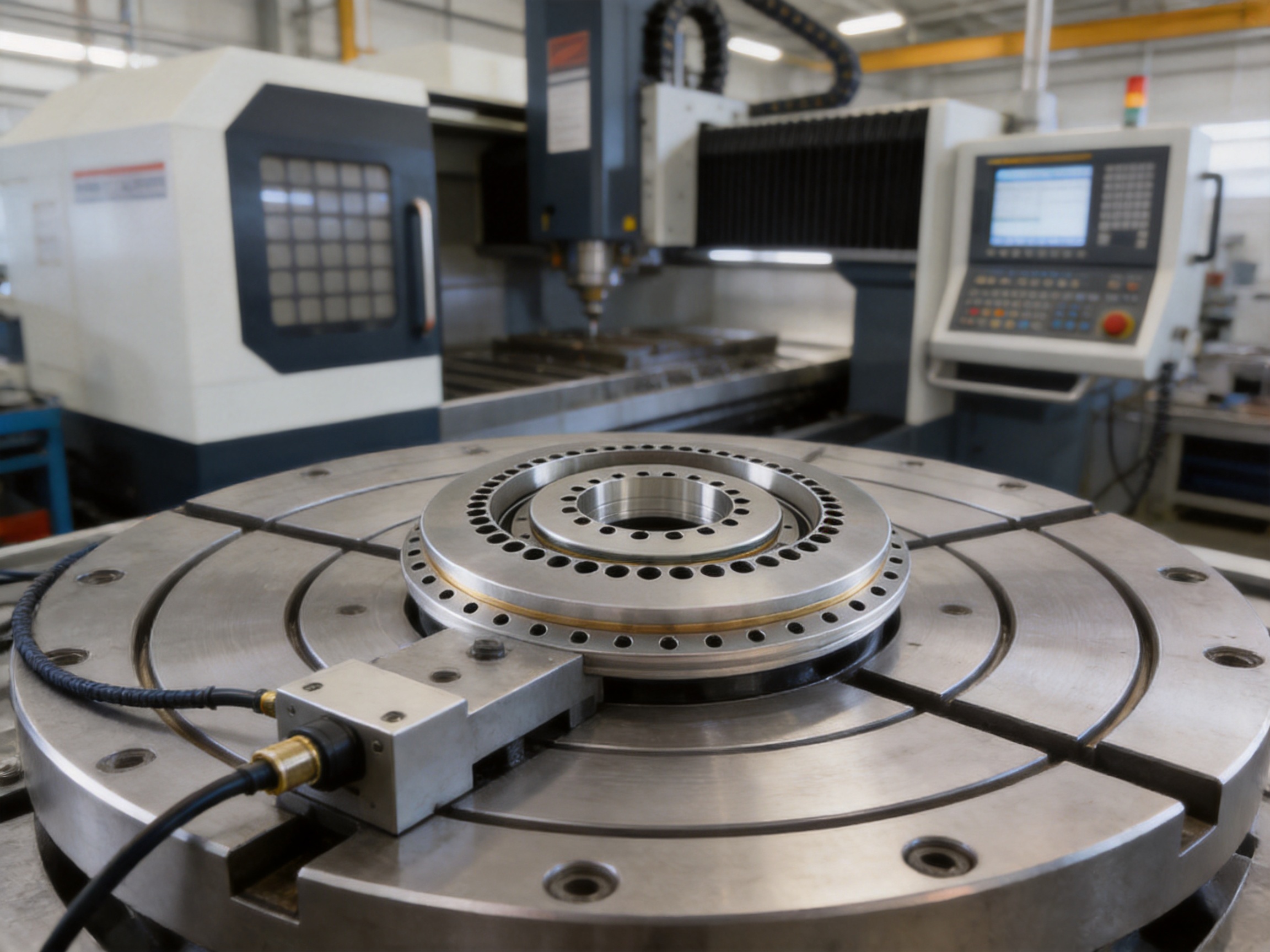
The most direct application for the YRTM angle measurement bearing is the high-precision CNC rotary table. A rotary table allows a workpiece to be indexed or continuously rotated while machining operations are performed. The bearing supplies mechanical support and the integrated measurement system provides angular feedback.
In indexing applications, the control system can move the table to a programmed angle and verify that the actual position has been reached. In continuous contouring applications, the feedback system supports coordinated motion between rotary and linear axes. This is important for turbine components, impellers, aerospace structures, molds, medical components, and other parts with complex curved surfaces.
Machining centers often combine multiple linear axes with one or more rotary axes. The rotary bearing must fit within the machine’s envelope while providing sufficient load capacity and stiffness. Its integrated measurement arrangement can reduce the need for a large external encoder assembly, which is useful when the rotary axis has limited space.
The non-contact inductive system is also suitable for environments where coolant and chips are present. The stated resistance to pollution and IP67 protection can help maintain reliable operation when the system is properly enclosed and installed. This contributes to reduced maintenance and fewer interruptions caused by contaminated measurement components.
Some machine tools use precision rotary bearings in spindle-related or auxiliary positioning assemblies. These systems may require high rotational accuracy, low friction, and stable feedback. The appropriate YRTM model can be selected according to space, speed, load, and moment requirements.
Because the bearing and angle measurement system are delivered as a coordinated solution, the machine builder can avoid developing a separate encoder mounting concept. This can shorten development time and make the mechanical design more repeatable across different machine models.
Industrial robots require compact, stiff, and reliable rotary joints. A joint may need to support a payload while maintaining accurate angular positioning through thousands or millions of operating cycles. The YRTM concept is applicable to robot axes that require integrated angular feedback and resistance to industrial contamination.
The absence of magnetic components can be useful in robotic cells containing strong motors, welding equipment, or other electromagnetic sources. The non-contact measurement principle also reduces concern about wear at the sensing interface. Engineers must still evaluate the bearing’s duty cycle, acceleration, shock loads, vibration, cable routing, and lubrication requirements.
Radar systems and antenna platforms often require precise azimuth or elevation movement. The bearing must support the antenna assembly while maintaining accurate rotational feedback. Environmental conditions may include wind loads, vibration, dust, moisture, and temperature variation. The integrated bearing and encoder can reduce system size and provide a stable reference for the control system.
Aerospace manufacturing and test equipment frequently require precise angular positioning. Rotary fixtures, inspection systems, assembly equipment, and simulation platforms may all benefit from accurate bearing guidance combined with high-resolution feedback. In such applications, material traceability, quality documentation, environmental qualification, and customized testing may be required in addition to the standard product specification.
Scientific instruments often require repeatable angular movement with low measurement uncertainty. Optical inspection systems, experimental platforms, coordinate-measurement assemblies, and laboratory positioning stages can use integrated angle measurement to reduce the number of separate mechanical and electrical interfaces.
The compact construction is especially beneficial where the instrument must maintain a large clear aperture or where the available installation space is restricted. The selected model should be matched carefully to the instrument’s mass, center of gravity, required angular resolution, and operating environment.
UKL Bearing Manufacturing Co., Ltd. presents itself as an integrated bearing manufacturer and trading company with capabilities covering research and development, production, and international distribution. The company reports a workforce of approximately 201 to 500 employees, more than 15 years of OEM and ODM export experience, and a production capacity of approximately 10,000 to 50,000 units per month.
For a precision product such as an angle measurement bearing, the importance of an integrated manufacturing structure is substantial. The mechanical bearing, measurement interface, sealing arrangement, and installation dimensions must work together. A supplier that can coordinate product development, machining, assembly, quality control, and technical support is better positioned to provide a consistent solution than a supplier that treats each component as an unrelated item.
The reported manufacturing process includes forging. Forging can provide a strong starting structure for bearing rings by shaping steel under controlled pressure. A suitable forged blank can support consistent grain flow and reduce the amount of material that must be removed during later machining operations.
Material selection and traceability are important at this stage. Bearing rings must withstand repeated rolling contact, load cycles, and dimensional requirements. Proper control of steel chemistry, cleanliness, forging temperature, deformation, and cooling helps establish the foundation for later heat treatment and grinding.
After forging, turning operations establish the basic geometry of the rings and other components. Modern turning equipment can control diameters, shoulders, grooves, mounting features, and reference surfaces. Stable machining practices reduce variation and prepare the components for heat treatment and final finishing.
For large-diameter rotary bearings, turning accuracy is particularly important because ring distortion can become more difficult to control as component size increases. Process planning, fixture design, cutting-tool management, and in-process inspection all contribute to dimensional consistency.
Heat treatment gives bearing steel the hardness and internal structure required for rolling contact. A controlled heat-treatment process can improve wear resistance, fatigue life, and dimensional stability. Parameters such as heating rate, holding time, atmosphere, quenching, tempering, and cooling must be managed carefully.
Heat treatment is also a potential source of distortion. For this reason, manufacturers of precision bearings must combine appropriate material selection with process control and subsequent machining allowances. The later grinding process is used to correct and refine the raceways and precision surfaces after the material has achieved the required properties.
Grinding is central to the production of precision bearing components. It provides accurate raceway geometry, controlled surface finish, and precise dimensional relationships between the inner ring, outer ring, and rolling elements. The quality of the grinding process directly influences friction, noise, rotation accuracy, load distribution, and service life.
For a rotary table bearing with integrated angle measurement, grinding accuracy also affects the mechanical reference used by the encoder. A stable and precise bearing geometry helps the measurement system perform consistently. Grinding equipment must therefore be supported by accurate dressing, coolant control, vibration management, and measurement feedback.
Assembly brings together the rings, rolling elements, spacers or cages, seals, measurement components, connectors, and other features. The bearing must be assembled with controlled cleanliness and correct internal geometry. Preload and clearance conditions should be verified according to the product design.
The angle measurement system requires additional care. Reading-head position, sensing gap, cable connection, signal quality, and rotational reference must be checked. The dual-reading-head arrangement must be aligned so that both channels provide useful and consistent data. Assembly technicians and quality engineers must understand both bearing technology and electronic measurement principles.
The company’s stated integration of R&D, production, and distribution can support communication between these disciplines. When a customer requires a customized mounting arrangement, special connector, modified signal output, or application-specific inspection report, an integrated engineering structure can make coordination more efficient.
UKL states that it uses digital production control to support product consistency. Digital records can help track work orders, process conditions, inspection results, material information, and assembly status. Such records are valuable for OEM customers that require repeatability across multiple production batches.
Quality assurance for an angle measurement bearing should include dimensional inspection, rotation testing, run-out measurement, load or stiffness verification where applicable, encoder signal testing, environmental sealing checks, and final visual inspection. The exact inspection plan depends on the model and customer requirements.
For international customers, documentation may include technical drawings, installation instructions, inspection certificates, packing records, and test reports. Clear documentation helps reduce commissioning time and supports traceability throughout the equipment’s service life.
A separate bearing and encoder arrangement can be effective, but it generally requires more design work. The machine builder must create an encoder mounting system, establish the correct radial and axial relationship, protect the scale from contamination, align the reading head, and determine how bearing deviation will influence the measured position.
The YRTM integrated design reduces these mechanical interfaces. The measurement system is developed around the bearing geometry, and the dual-reading-head principle provides a means of correcting radial deviation. This can improve installation efficiency and reduce the risk of mismatch between the bearing’s actual motion and the encoder’s reference.
Another advantage is space efficiency. A separate encoder may increase the outer diameter or height of the rotary assembly. In a compact robot joint or rotary table, that additional space may require a larger housing, longer cables, or a redesign of the workholding arrangement. An integrated solution can help preserve the original machine envelope.
Environmental protection is another comparison point. An exposed optical scale may require additional covers and cleaning provisions. A magnetic encoder may be vulnerable to magnetic-field conditions or demagnetization risks. The inductive YRTM measurement system avoids magnetic components and is designed for resistance to dust, oil, and other industrial contaminants, subject to correct installation.
The appropriate solution still depends on the application. Separate components may be preferred when a machine requires a non-standard diameter, a very specific encoder protocol, or independent replacement of the encoder. The benefit of the YRTM system is that it provides a coordinated, compact, and application-oriented alternative for users who prioritize mechanical integration and industrial durability.
Before installation, inspect the bearing, housing, shaft, mounting surfaces, fasteners, connectors, and cables. Confirm that the model designation, dimensions, hole pattern, signal output, and accessories match the machine design. Do not remove protective packaging until the work area is clean and prepared.
Mounting surfaces should be free from burrs, chips, rust, paint flakes, and other particles. Check the surface condition with appropriate precision instruments. Uneven support can distort the bearing rings, change the internal load distribution, and influence radial and axial run-out.
Fasteners should be installed according to the specified grade, quantity, tightening sequence, and torque. The supplied data lists M8 and M12 connection arrangements for the series, but the exact fastener pattern varies by model. The values in the technical tables should not be interpreted as a replacement for the official product drawing or installation manual.
During initial rotation, check for abnormal friction, noise, vibration, or uneven torque. Verify the encoder signal at low speed before increasing the operating speed. Confirm the direction of rotation, zero reference, signal amplitude, phase relationship, and controller scaling.
For a dual-reading-head system, compare both reading channels during slow rotation. Unexpected differences may indicate incorrect sensor gap, cable problems, mounting distortion, contamination, or controller configuration errors. Commissioning should include repeatability checks at several angular positions and, where possible, tests under representative loads.
Lubrication must follow the specified grease type, quantity, replenishment interval, and operating conditions. Excessive grease can increase friction and temperature, while insufficient lubrication can accelerate wear in the rolling contacts. Speed, load, temperature, and duty cycle should be considered together when establishing a maintenance schedule.
The non-contact encoder portion is designed to avoid wear at the sensing interface, but the bearing remains a precision mechanical component that requires appropriate care. Regular inspection should include noise, vibration, friction torque, temperature, run-out, signal stability, fastener condition, cable condition, and sealing integrity.
Changes in encoder output may indicate a wiring or controller issue, contamination, sensor-gap variation, bearing deformation, or mechanical damage. Troubleshooting should begin with the simplest causes, including connector seating, cable shielding, grounding, signal configuration, and mounting conditions.
Maintenance personnel should avoid applying excessive force to the bearing rings or encoder components. Tools should not contact sensitive measurement surfaces. If the bearing must be removed, the procedure should protect the raceways, mounting surfaces, reading heads, and cables.
Service life depends on load, speed, lubrication, contamination, shock, vibration, operating temperature, mounting accuracy, and maintenance. A bearing operating below its rated capacity in a clean, properly lubricated environment will normally experience different service conditions from one exposed to frequent overload, impact, coolant, and rapid acceleration.
Different rotary applications often require more than a standard catalog selection. Customers may need customized mounting interfaces, special cable lengths, connector configurations, signal formats, preload arrangements, inspection documentation, or integration assistance. The manufacturer’s OEM and ODM experience can support such projects from initial design through production and delivery.
UKL reports that its multilingual service team provides technical response, installation guidance, and after-sales maintenance support worldwide. This is important for international equipment builders that need communication across design, procurement, assembly, and service departments.
Technical discussions should include the bearing model, load spectrum, maximum speed, acceleration, overturning moment, operating temperature, contamination, lubrication, desired accuracy, controller type, output signal, installation orientation, and expected service life. Providing complete application information helps the supplier recommend a suitable configuration rather than selecting a bearing based only on bore diameter.
Precision bearing production requires stable processes, skilled personnel, reliable equipment, and consistent inspection. A company with multiple production stages under coordinated management can improve control over quality and delivery. UKL describes production lines covering forging, turning, heat treatment, grinding, assembly, and packaging.
The company also identifies sustainability as a long-term commitment. Reported initiatives include material recycling, energy optimization, and environmentally responsible processes. Although sustainability performance should be evaluated using project-specific evidence and measurable data, attention to material efficiency and energy consumption can support responsible industrial manufacturing.
Global supply capability is valuable for OEM customers that operate production facilities in several countries. UKL reports exports to the United States, Italy, Germany, Poland, South Africa, Egypt, India, and other regions. International supply requires careful packaging, documentation, customs coordination, technical communication, and after-sales support.
For large and heavy rotary bearings, packaging is particularly important. The product should be secured against shock, vibration, moisture, and movement during transport. The package should preserve the bearing’s protective coating and prevent damage to connectors, cables, and precision mounting surfaces.
Start with the required bore diameter and outside diameter. The available installation space should be checked in three dimensions, including the height occupied by the bearing, encoder connections, cable routing, seals, and adjacent components.
Next, calculate the applied axial force, radial force, and overturning moment. Include the mass of the workpiece, fixture, rotary table, tool, and any eccentric payload. Cutting forces, acceleration forces, braking forces, and emergency-stop loads should be included where relevant.
Compare the calculated loads with the dynamic and static ratings. Dynamic ratings relate to repeated operating conditions, while static ratings are important for permanent deformation risk during stationary or low-speed loading. The application should not be evaluated using only one rating.
Review the speed requirement and duty cycle. The listed grease-lubricated limiting speed is not necessarily the recommended speed for every load condition. High speed combined with large loads, rapid acceleration, or high ambient temperature may require a lower operating limit.
Specify the required angle accuracy and controller interface. Confirm whether the application needs sine-wave 1 Vpp output, TTL output, a particular connector, or compatibility with a specific CNC control system. Check whether interpolation and compensation functions are available in the controller.
Finally, review the environment. Consider dust, oil, coolant, humidity, cleaning chemicals, vibration, shock, temperature, and electromagnetic conditions. The IP67 rating is beneficial, but the entire installation must maintain the intended protection level.
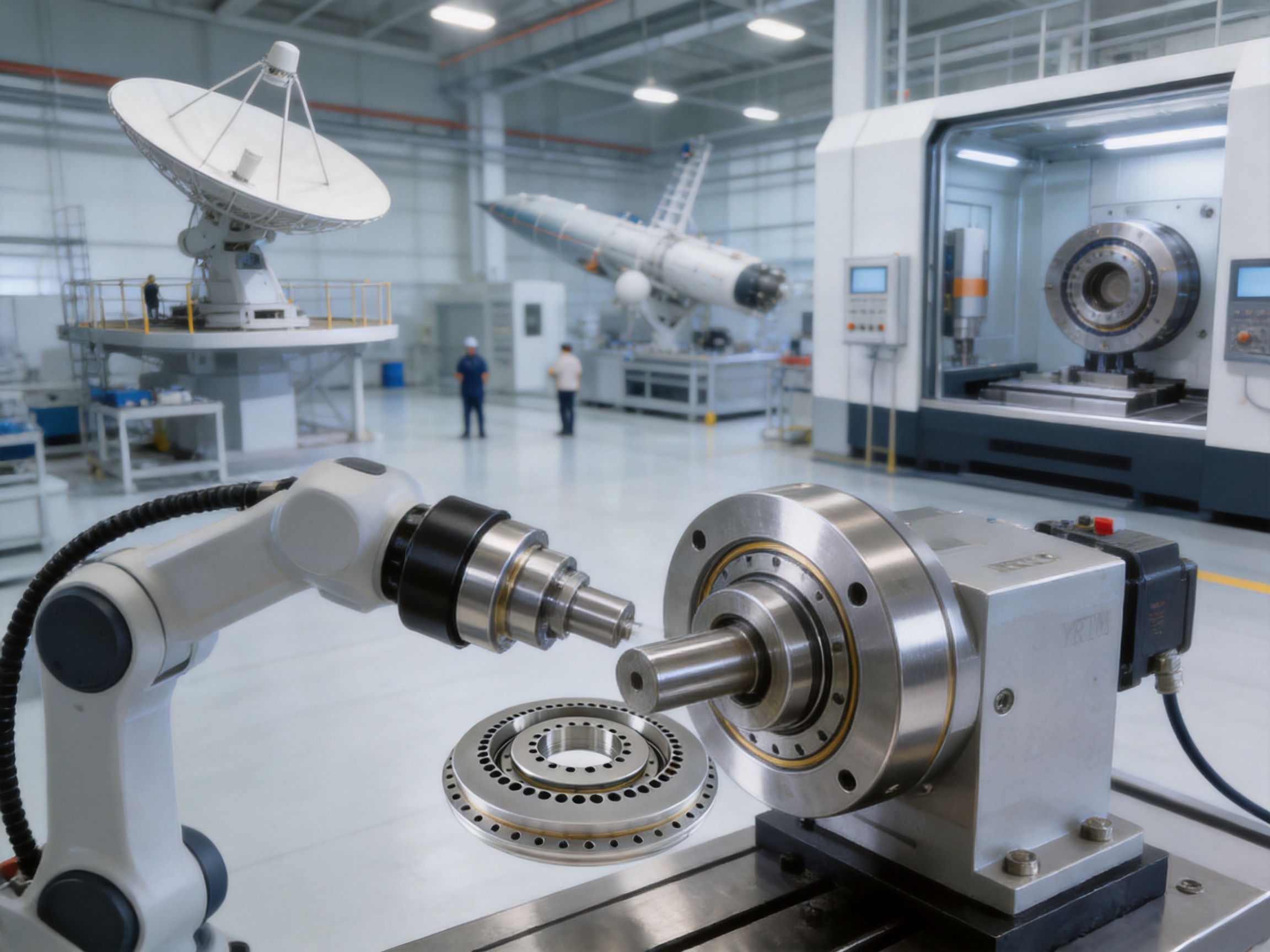
It is a precision rotary table bearing combined with an integrated non-contact inductive angle measurement system. It supports axial loads, radial loads, and overturning moments while providing angular-position feedback to a controller.
Two reading heads observe the measurement element from different positions. Comparing their signals allows the system to identify and correct certain bearing radial deviations in real time, reducing the possibility that radial movement will be interpreted as an angular-position error.
The system uses a non-contact inductive measurement principle. It does not rely on magnetic components or magnetic tape and is not an optical encoder.
Yes. The rolling elements and raceways require the specified lubrication. The encoder sensing interface is non-contact and wear-free, but the mechanical bearing still requires correct grease, quantity, and maintenance according to the technical documentation.
The product information states that the system can output 1 Vpp sine-wave or TTL square-wave signals and is compatible with Siemens and FANUC CNC systems. The exact interface must be confirmed for the selected model and controller configuration.
IP67 indicates protection against dust ingress and temporary immersion under defined test conditions. Actual performance depends on correct installation, cable routing, connectors, seals, and environmental exposure. High-pressure coolant and aggressive chemicals require additional evaluation.
Yes. The compact structure, integrated angular feedback, load capacity, and resistance to industrial contamination make it suitable for selected robotic joints and rotary axes. The model must be checked against payload, moment, acceleration, shock, vibration, speed, and service-life requirements.
The listed series includes YRTM150, YRTM180, YRTM200, YRTM260, YRTM325, YRTM395, and YRTM460. Nominal bore sizes range from 150 mm to 460 mm. Other configurations should be confirmed with the manufacturer.
The standard information identifies 1 Vpp and TTL outputs. Customized signal, connector, cable, or mounting requirements may be discussed with the manufacturer during the engineering and quotation process.
Provide the required model or dimensions, axial and radial loads, overturning moment, speed, acceleration, duty cycle, accuracy target, mounting orientation, environmental conditions, lubrication method, controller type, signal output, and documentation requirements.
An integrated assembly can reduce installation space, simplify alignment, decrease the number of mechanical interfaces, and improve the relationship between bearing motion and angular feedback. Separate systems may still be appropriate for non-standard applications, but the integrated design is advantageous when compactness and coordinated accuracy are priorities.
The YRTM angle measurement bearing addresses a central challenge in modern rotary equipment: achieving accurate angular feedback while supporting demanding mechanical loads in a compact and durable assembly. Its non-contact inductive encoder, dual-reading-head correction system, high resolution, resistance to magnetic effects, industrial protection, and flexible signal output make it a strong solution for precision rotary tables and related equipment.
Compared with a conventional arrangement using a separate bearing and encoder, the integrated design can simplify machine architecture, reduce installation space, and improve the connection between mechanical rotation and measured position. Its ability to support axial loads, radial loads, and overturning moments also makes it suitable for heavy and dynamically loaded rotary axes.
The performance of any precision bearing depends on correct selection, mounting, lubrication, electrical integration, and machine-level design. When these factors are controlled, the YRTM series can support high-precision CNC machining, robotics, radar positioning, aerospace equipment, scientific instruments, and other demanding applications.
UKL Bearing Manufacturing Co., Ltd. strengthens the product offering through integrated R&D, forging, turning, heat treatment, grinding, assembly, digital production control, packaging, and international technical service. Its OEM and ODM experience provides a foundation for standard and customized bearing solutions. For equipment builders seeking a compact rotary bearing with integrated angle measurement, the YRTM series offers a practical combination of mechanical capacity, measurement performance, environmental resistance, and manufacturing support.
1. UKL Bearing Manufacturing Co., Ltd., YRTM Angle Measurement Bearing Product Information and Technical Tables.
2. UKL Bearing Manufacturing Co., Ltd., Company Manufacturing and Engineering Profile.
3. General principles of rolling-bearing selection, load rating, lubrication, mounting, and service-life evaluation.
4. General principles of inductive angular-position measurement and dual-reading-head error compensation.
5. General industrial guidance for IP67 enclosure protection, CNC encoder integration, signal shielding, and machine commissioning.
Product Categories
Contact Us

Jane@ukl-bearing.com
Jenny@ukl-bearing.com
Andy@ukl-bearing.com
Ivy@ukl-bearing.com

+86-510- 88763239
+86-15371057968

No.1 Hehuan Road, Hudai Town, Binhu District, Wuxi City.
Ready to Begin?
Get in Touch

Now!
UKL BEARING
 English
 Español
 русский